Active Antenna for Medium Wave
Circuit : David Sayles
Text : Andy Collinson
Email: All enquiries via
anc@mitedu.freeserve.co.uk
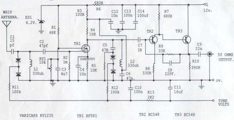
Medium Wave Active Antenna schematics
NotesThis circuit is designed to amplify the input from a telescopic whip antenna. The preamplifier is designed to cover the medium waveband from about 550Khz to 1650Khz. The tuning voltage required is 1 to 12 volts and can be obtained from a 10k potentiometer connected to the 12 Volt power supply.
RV1 is the gain control allowing weak signals to be amplified or strong signals to be attenuated. The control voltage is applied to gate 2 of TR1, a dual-gate MOSFET, the signal voltage applied via gate 1; the input signal being tuned via L1 and the two varicap diodes at the MOSFET's input and also by L2 and the varicaps at the MOSFET's drain terminal. Both tuned circuits provide high selectivity across the entire tuning range. To aid stability the MOSFET stage is fed from a stabilized supply consisting of ZD1 and R6.
To drive low impedance (50 ohm) receivers, the medium output imepedance of the BF981 stage is enhanced by the composite amplifier made from TR2 and TR3. TR2 is operating in common emitter boosting voltage levels by just over 2, TR3 is operating in emitter follower giving the circuit a low output impedance.
Finally this active antenna can be used on other bands by changing the values of L1 and L2. To perform on multiple bands switches or relays can be used to change the value of L1 and L2.
Title: Active Antenna for Medium Wave
electronic circuit
Source: unknown
Published on: 2006-01-15
Reads: 3465
Print version: ![]()
Other electronic circuits and schematics from RF circuit
-
Long range FM transmitter
-
15W Fm-transmitter
-
FM voice transmitter for Band 2 VHF
-
Sensitive Field Strength Meter
-
FM transmitter
-
Micro Power AM Broadcast Transmitter
-
FM Transmitter with Opamp
-
ZN414 Portable AM Receiver
-
Bipolar Regenerative receiver
-
1 Watt C-Class RF Amplifier