Measuring current and voltageElectronics guide > Measuring current and voltage
There’s not too much to buy for this chapter of Starting Electronics. As usual there’s a small number of resistors:
- 2 x lk5
- 1 x 4k7
- 2 x 100 k
As before, power ratings and tolerance of these resistors are not important.
We’re looking at current and voltage in our experiments in this chapter, so you’ll need to have a voltage and current source. The easiest and cheapest method is a simple battery. PP3, PP6, or PP9 sizes are best — as we need a 9 V source.
Whichever battery you buy, you’ll also need its corresponding battery connectors. These normally come as a pair of push-on connectors and coloured connecting leads. The red lead connects to the positive battery terminal; the black lead connects to the negative terminal.
The ends of the connecting leads furthest from the battery are normally stripped of insulation for about the last few millimetres or so, and tinned. Tinning is the process whereby the loose ends of the lead are soldered together. If the leads are tinned you’ll be able to push them straight into your breadboard. If the leads aren’t tinned, on the other hand, don’t just push them in because the individual strands of wire may break off and jam up the breadboard. Instead, tin them yourself using your soldering iron and some multicored solder. The following steps should be adhered to:
- twist the strands of the leads between your thumb and first finger, so that they are tightly wound, with no loose strands,
- switch on the soldering iron. When it has heated up, tin the iron’s tip with multicore solder until the end is bright and shiny with molten solder. If necessary, wipe off excess solder or dirt from the tip, on a piece of damp sponge; keep a small piece of sponge just for this purpose,
- apply the tip of the iron to the lead end, and when the wires are hot enough apply the multicore solder. The solder should flow over the wires smoothly. Quickly remove the tip and the multicore solder, allowing the lead to cool naturally (don’t blow on it as the solder may crack if it cools too quickly). The lead end should be covered in solder, but no excess solder should be present. If a small blob of solder has formed on the very end of the lead, preventing the lead from being pushed into your breadboard, just cut it off using your side cutters.
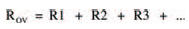
We’ll start our study, this chapter, with a brief recap of the ideas we covered in the last chapter. We saw then that resistors in series may be considered as a single equivalent resistor, whose resistance is found by adding together the resistance of each resistor. This is called the law of series resistors, which is given mathematically by:
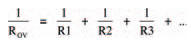
Similarly, there is a law of parallel resistors, by which the single equivalent resistance of a number of resistors connected in parallel is given by:
Using these two laws many involved circuits may be broken down, step by step, into an equivalent circuit consisting of only one equivalent resistor. The circuit in Figure 2.9 last chapter was one such example and, if you remember, your homework was to calculate the current I from the battery. To do this you first have to find the single equivalent resistance of the whole network, then use Ohm’s law to calculate the current.
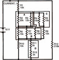
Figure 3.1 A resistor network in which the total resistance can only be calculated by breaking it down into blocks
Figure 3.1 shows the first stage in tackling the problem, by dividing the network up into a number of smaller networks. Using the two expressions above, associated with resistors in series and parallel, we can start to calculate the equivalent resistances of each small network as follows:
Network A
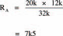
Network A consists of two resistors in parallel. The equivalent resistance, RA, may therefore be calculated from the above expression for parallel resistors. However, we saw in the last chapter that the resistance of only two parallel resistors is given by the much simpler expression:
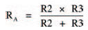
which gives:
Network B
Three equal, parallel resistors form this network. Using the expression for parallel resistors we can calculate the equivalent resistance to be:
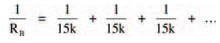
which gives:

Hint:
This is an interesting result, as it shows that the equivalent resistance of a number of equal, parallel resistors may be easily found by dividing the resistance of one resistor, by the total number of resistors. In this case we had three, 15 k resistors, so we could simply divide 15 k by three to obtain the equivalent resistance. If a network has two equal resistors in parallel, the equivalent resistance is one half the resistance of one resistor (that is, divide by 2). If four parallel resistors form a network, the equivalent resistance is a quarter (that is, divide by 4) the resistance of one resistance of one resistor. Hmm, very useful. Must remember that — right?
Network C
Using the simple expression for two, unequal parallel resistors:

Network D
The overall resistance of two series resistors is found by adding their individual resistances. Resistance RD is therefore 10 k.
We can now redraw the whole network using their equivalent resistances, as in Figure 3.2, and further simplify the resultant networks.
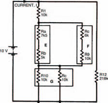
Figure 3.2 The same network, broken down into smaller networks using equivalent resistances (networks E, F and G)
Network E
This equivalent resistance is found by adding resistances RA and RB. It is therefore 12k5.
Network F
Same as network E. Resistance RF = 16 k.
Network G
Two equal parallel resistors, each of 10 k. Resistance RG is therefore 5 k. Figure 3.3 shows further simplification.
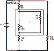
Figure 3.3 The network further simplified (network H) into two unequal parallel resistances
Network H
Two unequal, parallel resistors. Resistance RH is therefore given by:
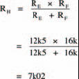
Figure 3.4 shows a further simplification.
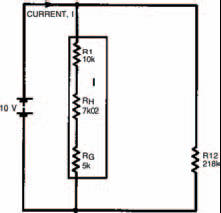
Figure 3.4 The network simplified into a string of series resistances (network I)
Network I
Resistance RI is found by adding resistances of resistors R1, RH and RG. Resistance RI is therefore 22k02.
Figure 3.5 shows the next stage of simplification with two unequal parallel resistors. The whole network’s equivalent resistance is therefore given by:

Now, from Ohm’s law we may calculate the current I, flowing from the battery, using the expression:
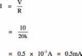
Did you get the same answer?
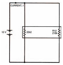
Figure 3.5 The final simplification, into two parallel resistances. From this the current can be calculated
One man’s meter ....
Of course, there is another way the current I may be found. Instead of calculating the equivalent resistance of the network you could measure it using your multi-meter. But first you would need to obtain resistors of all the values in the network. Then you must build the network up on breadboard, with those resistors.
Take note
The measured result may not, unfortunately, be exactly the same as the calculated result — due to resistor tolerances and multi-meter tolerance.
Finally, from this measured result and Ohm’s law, the current I may be calculated.
Hint:
Your multi-meter can be used directly to measure current (it’s a multimeter, remember) so after building up your network of resistors you can simply read off the current flowing. Figure 3.6 illustrates how a multi-meter should be connected in a circuit to allow it to indicate the current through the circuit. Note the use of the words in and through. In chapter 1 we looked closely at current and saw that it is a flow of electrons around a circuit. To measure the current we must position the multi-meter in the circuit — in other words the current going around the circuit must also go through the multi-meter. This is an important point when measuring current. Remember it!
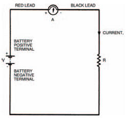
Figure 3.6 A diagram showing a meter connected in circuit, with the red lead at the point of higher potential
Take note
If you are using an analogue multi-meter, make sure you have your leads the correct way round. When the current through the multi-meter flows in the right direction the movement and pointer turn clockwise. In the wrong direction on the other hand, the movement and pointer attempts to turn anti-clockwise. At best you won’t get a valid measurement of current if the multi-meter is the wrong way round — at worst you’ll damage the movement.
A digital multi-meter, however, will merely give a negative reading.
But what is the right way round? And how do you tell the difference? The answers are quite simple really; both given by the fact that your multi-meter has two leads, one red, one black. The colour coding is used to signify which lead to connect to which point in a circuit. By convention, black is taken to be the colour signifying a lower potential. Red, also by convention, signifies a higher potential. So, the multi-meter should be connected into the circuit with its red lead touching the point of higher potential and the black lead touching the point of lower potential. This is illustrated in Figure 3.6 with symbols close to the multi-meter (+ for the red lead, – for the black). In the circuit shown, the point of higher potential is the side of the circuit to the positive terminal of the battery (also marked +).
It doesn’t matter where in the circuit the multi-meter is placed, the red lead must always connect to the point of higher potential. Figure 3.7, for example, shows the multi-meter at a different position, but the measurement is the same and the multi-meter won’t be damaged as long as the red lead is connected to the point of higher potential.
Negative vibes
Figures 3.1 to 3.7 all show current flowing from the positive terminal of the battery to the negative terminal. Now we know that current is made up of a flow of electrons so we might assume that electrons also flow from positive to negative battery terminals. We might — but we’d be wrong, because electrons are actually negatively charged and therefore flow from negative to positive battery terminals. But a negative flow in one direction is exactly the same as a positive flow in the opposite direction (think about it!) so the two things mean the same. However, it does mean that we must define which sort of current we are talking about when we use the term. Figure 3.8 defines it graphically: conventional current (usually called simply current) flows from positive to negative; electron current flows from negative to positive. Whenever we talk about current from now on, you should take it to mean conventional current.
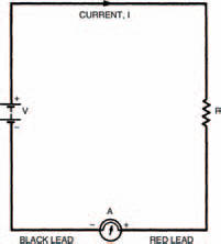
Figure 3.7 The meter connected to a different part of the circuit. The effect is the same as long as the red lead is correctly connected
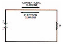
Figure 3.8 Conventional current travels from positive to negative; electron current travels in the opposite direction
<< More and more complex circuits