ICs, oscillators and filtersElectronics guide > ICs, oscillators and filters
You’ll need a number of different components to build the circuits this chapter, some of them you’ll already have, but there are a few new ones, too. First, the resistors required are:
- 1 x 1k5
- 1 x 4k7
- 1 x 10 k
Second, capacitors:
- 1 x 1 nF
- 2 x 10 nF
- 2 x 100 nF
- 1 x 1 μF electrolytic
- 1 x 10 μF electrolytic
Power ratings, tolerances and so on, of all these components are not critical, but the electrolytic capacitors should have a voltage rating of 9 V or more.
Some other components you already have: a switch, battery, battery connector, breadboard, multi-meter, should all be close at hand, as well as some single-strand tinned copper wire. You are going to use the single-strand wire to make connections from point-to-point on the breadboard, and as it’s uninsulated this has to be done carefully, to prevent short circuits. Photo 5.1 shows the best method. Cut a short length of wire and hold it in the jaws of your snipe-nosed or long-nosed pliers. Bend the wire round the jaws to form a sharp right-angle in the wire. The tricky bit is next — judging the length of the connection you require, move the pliers along the wire and then bend the other end of the wire also at right angles round the other side of the jaws (Photo 5.2).
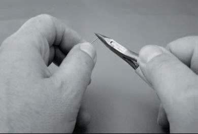
Photo 5.1 Take a short piece of wire between the jaws of your pliers…
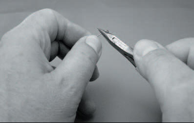
Photo 5.2 …and bend it carefully into two right angles, judging the length
If you remember that the grid of holes in the breadboard are equidistantly spaced at 2.5 mm (or a tenth of an inch if you’re old-fashioned like me — what’s an inch, Grandad?) then it becomes easier. A connection over two holes is 5 mm long, over four holes is 10 mm long and so on — you’ll soon get the hang of it.
Now, holding the wire at the top, in the pliers, push it into the breadboard as shown in Photo 5.3, until it lies flush on the surface of the breadboard as in Photo 5.4. No bother, eh? Even with a number of components in the breadboard it is difficult to short circuit connections made this way.
Two other components you need are:
- 1 x 555 integrated circuit
- 1 x light emitting diode (any colour).
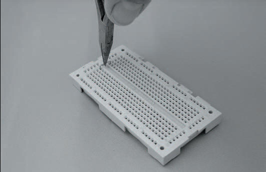
Photo 5.3 The wire link you have made should drop neatly into the breadboard
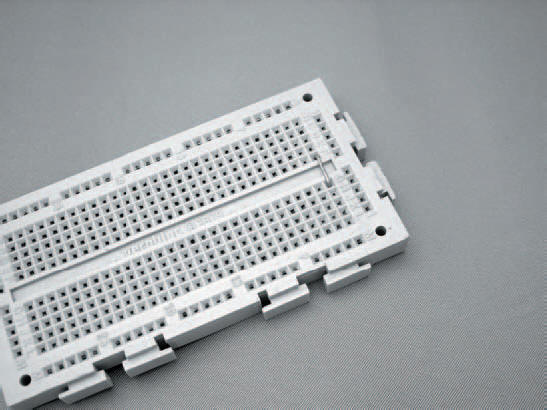
Photo 5.4 If the link is a good fit. It can be used over and over again in different positions
We’ve seen an integrated circuit (IC) before and we know what it looks like, but we’ve never used one before, so we’ll take a closer look at the 555 now. It is an 8-pin dual-in-line (DIL) device and one is shown in Photo 5.5. Somewhere on its body is a notch or dot, which indicates the whereabouts of pin 1 of the IC as shown in Figure 5.1. The remainder of the pins are numbered in sequence in an anti-clockwise direction around the IC.
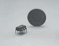
Photo 5.5 The 555, an 8 pin DIL timer IC, beside a UK one penny piece
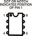
Figure 5.1 A diagram of the normal configuration of any IC: the dot marks pin 1 and the remaining pins run anti-clockwise
ICs should be inserted into a breadboard across the breadboard’s central bridged portion. Isn’t it amazing that this portion is 7.5 mm across and, hey presto, the rows of pins of the IC are about 7.5 mm apart? It’s as if the IC was made for the breadboard! So the IC fits into the breadboard something like that in Photo 5.6.
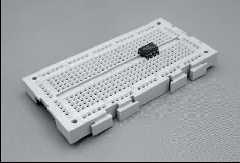
Photo 5.6 The IC mounted across the central divide in the breadboard, which is designed to be the exact size
We’ll look at the light emitting diode later.
If you remember, last chapter we took a close look at capacitors, how they charge and discharge, storing and releasing electrical energy. The first thing we shall do this chapter, however, is use this principle to build a useful circuit called an oscillator. Then, in turn, we shall use the oscillator to show some more principles of capacitors. So, we’ve got a two-fold job to do now and there’s an awful lot of work to get through — let’s get started.
Figure 5.2 shows the circuit of the oscillator we’re going to build. It’s a common type of oscillator known as an astable multi-vibrator. The name arises because the output signal appears to oscillate (or vibrate) between two voltages, never resting at one voltage for more than just a short period of time (it is therefore unstable, more commonly known as astable). An astable multi-vibrator built from discrete that is, individual components, can be tricky to construct so we’ve opted to use an integrated circuit (the 555) as the oscillator’s heart.
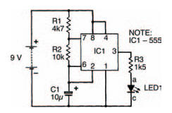
Figure 5.2 The circuit of the astable multi-vibrator circuit using the 555
Inside the 555 is an electronic switch which turns on when the voltage across it is approximately two-thirds the power supply voltage (about 6 V in the circuit of Figure 5.2), and off when the voltage is less than one-third the power supply voltage (about 3 V). Figure 5.3(a) shows an equivalent circuit to that of Figure 5.2 for the times during which the electronic switch of the 555 is off.
You should be able to work out that the capacitor C1 of the circuit is connected through resistors R1 and R2 to the positive power supply rail. The time constant τ1 of this part of the circuit is therefore given by:

When the voltage across the switch rises to about 6 V, however, the switch turns on (as shown in Figure 5.3(b), forming a short circuit across the capacitor and resistor, R2. The capacitor now discharges with a time constant given by:

Of course, when the discharging voltage across the switch falls to about 3 V, the switch turns off again, and the capacitor charges up once more. The process repeats indefinitely, with the switch turning on and off at a rate determined by the two time constants. Because of this up and down effect such oscillators are often known as relaxation oscillators.
As you might expect the circuit integrated within the 555 is not just that simple and there are many other parts to it (one part, for example, converts the charging and discharging exponential voltages into only two definite voltages — 9 V and 0 V — so that the 555’s output signal is a square wave, as shown in Figure 5.3(c). But the basic idea of the astable multi-vibrator formed by a 555 is just as we’ve described here.
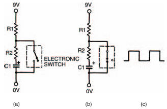
Figure 5.3 (a) shows a circuit equivalent to Figure 5.2 when the 555’s switch is off; (b) shows the circuit when the switch is on; (c) shows the square wave output signal
<< Capacitance values