Diodes IElectronics guide > Diodes I
We’re going to take a close look at a new type of component this chapter — the diode. Diodes are the simplest component in the range of devices known as semiconductors. Actually, we’ve briefly looked at a form of diode before: the light-emitting diode, or LED, and we’ve seen another semiconductor too: the 555 integrated circuit. But now we’ll start to consider semiconductors in depth.
Naturally, you’ll need some new components for the circuits you’re going to build here. These are:
- 1 x 150 Ω, 0.5 W resistor
- 1 x 1N4001 diode
- 1 x OA47 diode
- 1 x 3V0 zener diode (type BZY88)
- 1 x 1k0 miniature horizontal preset
Diodes get their name from the basic fact that they have two electrodes (di — ode, geddit?). One of these electrodes is known as the anode: the other is the cathode. Figure 6.1 shows the symbol for a diode, where the anode and cathode are marked. Figure 6.2 shows some typical diode body shapes, again with anode and cathode marked.
Photo 6.1 is a photograph of a miniature horizontal preset resistor. We’re going to use it in the following circuits as a variable voltage divider. To adjust it you’ll need a small screwdriver or tool to fit in the adjusting slot — turning it one way and another alters position of the preset’s wiper over the resistance track.

Figure 6.1 The circuit symbol for an ordinary diode
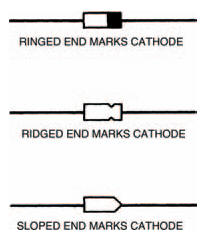
Figure 6.2 Some typical diode body shapes
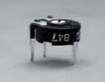
Photo 6.1 A horizontal preset resistor
Figure 6.3 shows the circuit we’re going to build first this chapter. It’s very simple, using two components we’re already familiar with (a resistor and an LED) together with the new component we want to look at: a diode. Before you build it, note which way round the diode is and also make sure you get the LED polarised correctly, too. In effect, the anodes of each diode (a LED is a diode, too, remember — a light emitting diode) connect to the more positive side in the circuit. A breadboard layout is shown in Figure 6.4, though by this stage you should perhaps be confidently planning your own breadboard layouts.
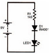
Figure 6.3 Our first simple circuit using a diode
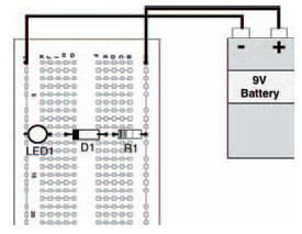
Figure 6.4 A breadboard layout for the circuit in Figure 6.3
<< Filter Tips