20dB VHF Amplifier
| Manufacture: Soulis Papanastasiou |
| Copyright: Technical Election (T420 Dec 01) |
| Cost of manufacture: 6 ? |
Note: The text is AUTO translated from Greek version
Many times we needed to strengthen a small signal in the region of VHF or FM, or it is we lead a body, or a receptor. The preamplifier that to you we propose offers 20dB in all the region of VHF and it still can reach also their 500MHZ.
The amplifier is a circuit of high frequency RF with distinguishable materials. The amplifier as circuit strengthens the tendency of signal with concrete aid, depending on the frequency of signal. If the frequency of signal is included in the limits of spectrum of frequencies of amplifier, then it is strengthened, otherwise it is downgraded. Each amplifier of this category, accordingly with his designing, strengthens a concrete region of frequencies and obeys in same characteristics. The one that to you we present today concerns the regions of VHF where they exist and the corresponding television stations for channels 5 until 12. His circuit he is enough simple, so that it is made easily with materials that exist in the trade. It is based on transistors with aid until the 500MHZ. The type of transistor can be BF197 or some other.
Theoretical circuit
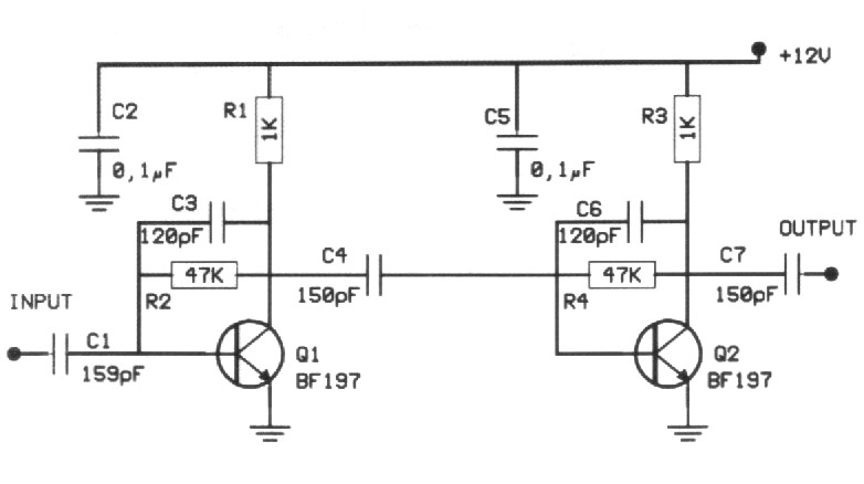
In form 1 appears the theoretical circuit of amplifier. As we see it is constituted from two similar circuits (rungs). In this circuits are not included in joint action circuits. With that way is covered a wide spectrum of frequencies, without is differentiated abruptly the aid as for the frequency. With this provision we have smaller gain but big breadth of frequencies. The two rungs are same, with the same prices of materials and each rung offer aid roughly 10dB. The transistors and the remainder materials, because the industrial manufacture, have almost the same characteristics. Associates the particular characteristics of demagogues are altered mainly the aid of rung. Each rung uses a transistor of type npn in provision of common emitter that functions in order A. his rungs works in provision of common emitter with null resistance in emitter. In each rung a network of resistances between the collectors and the bases polarize the transistors and ensures the operation of circuit. The junction between the rungs becomes via ceramic capacitors of small capacity from 0,1nF until 0,22nF (at preference ceramic). In the place of two rungs we can try various transistors of independent company or even different between them. The circuit of course cannot work with all of them. The tendency of catering should emanate from stabilised power supply with tendency 12V. Depending on the tendency of catering and the type of transistor, in each rung of amplifier it needs enter also different resistances. Force of expense, under conditions of high excitation it can exceed the 1 mW
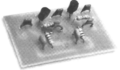
Manufacture
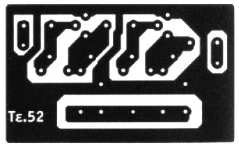
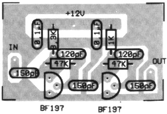
The total aid of circuit, according to the elements of transistors, reaches 20dB. Enough aid for a lot of applications. The amplifier is drawn in order to it has big response of frequency up to 0,5Ghz. According to the particular characteristics of manufacture, the better application that we could to you propose for this designing would be the aid of television signal emanating from a small transmitter of television or the preamplifier of a frequency meter. The assembly of amplifier is realised above in printing form 2. In this you will place all the materials according to form 3. The manufacture, in order to it works right it needs one small stabilised power supply 12V. The consumption of circuit is small hardly some mA. The resistance en line with the collector is 10 000. When you finish the construction and the control of manufacture, place the PCB in metal box of suitable dimensions.
|
|
|
PARTS
| R1 = 1K | C3 = 120pF |
| R2 = 47K | C4 = 150pF |
| R3 = 1K | C5 = 0,1uF |
| R4 = 47K | C6 = 120pF |
| C1 = 150pF | C7 = 150pF |
| C2 = 0,1uF | Q1 = Q2 = BF197 |
E-mail: steve_filianos@hotmail.com for questions - info.
Title: 20dB VHF Amplifier
electronic circuit
Source: www.electronics-lab.com
Published on: 2005-02-03
Reads: 18536
Print version: ![]()
Other electronic circuits and schematics from RF circuit
-
Low-Frequency Crystal Controlled Oscillator
-
Video Signal Amplifier
-
Field Strength Meter
-
Transmitter FM 45W with valve
-
Coilless FM transmitter
-
MK484 Portable Receiver
-
Low Distortion Crystal Oscillator
-
VHF Audio Video Transmitter
-
VHF Video Transmitter
-
2 Transistor FM Voice Transmitter