15W Fm-transmitter
It was five years ago when I did an attempt to build my first fm-transmitter.
It ended in a giant faillure. The only thing it did was interferring with our
tv-set. Looking back it was due to the lack of information I had. A schematic
was my only help. Now, five years later, I know a lot more about
electro-technics. So I searched for a schematic of a stable, tested fm-transmitter
with a far reach. I will put all information you'll have to know in my page. I
made drawings to make things clearer. As said before: I'm still building it, so
I will add information every time I made progress. It would be wise for you out
there not to start building untill I'm ready and have tested it. It has been
succesfully built before, but my succes will give you a double security. I
remind you of the fact that I can also fail.
Intro
Building a good fm-transmitter(88-110Mhz) begins with getting a good
schematic. You don't have to understand the precise working of the transmitter
to build it. But some basic information won't harm. A transmitter alone is, as
you probably know, is not enough to start your radio-station. In the simplest
form you need 4 things. First an input device such as an amplifiler you also use
with your home-stereo.
You can also use a walkman. Details about input-devices in the page: "Input".
Second you need a regulated power-supply. In this case a 14-18 Volts/2,5-3,5
Ampere. One of the most influencial things you need is antenna and coax-cable.
More about this later on. And finally the transmitter itself. You can devide the
transmitter in two main parts: the oscilator and the amplifiler. The oscilator
converts electric sound information into electromagnetic waves. The amplifiler
gives these waves
a bigger amplitude.
Building
It's stable and has output of 15-18 watts. This enough to terrorize your wide
surroundings at the fm-band.
The most often used technique to connect the components to each other is soldering them on a double sided copper-board. Another way is connecting the components floating. It is cheaper but very tricky. Below you see the copper-board layout(PCB). I designed it looking closely at the root scheme.
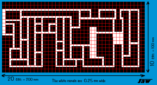
Full size PCB:
PCBGRID.GIF
To get this pattern in copper surface you use a acid bath. Use a water-resistant
permanent marker to paint your own copper-board black in the pattern the shown
above. Color the back side ompletely black. The grid-squares are 0,5*0,5 cm each.

When the acid has eaten the non-painted copper away you must remove the
complet thin layer of black paint with sandpaper. Don't remove too much copper
with it.
So, now you have the surface to solder the electric components on.
Now a few basic rules for good soldering:
1. Use a special electronics-solderingrod with a slim top.
2. Use soldering-metal with an anti-oxidant-fluid core.
3. Don't heat the components! Heat the connection-point on your PCB.
4. Make sure that the surface is not too smooth.
5. Don't use too much metal.
6. Don't let the soldering metal form a bridge beetween two copper-surfaces.
7. If you're smart you start from the middle of your prepaired board.
In this way you'll have enough space.
Below the schematic. The yellow lines are pieces of copperboard that devide the
transmitter in 3 parts. This is essential. Without them, internal interferrence
will ruin your signal.
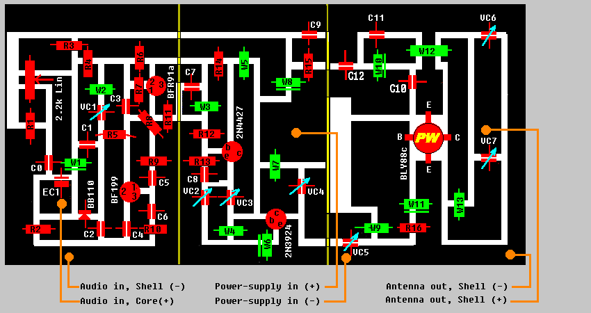
This picture is the coldwater-version... For the detailled version:
PCBCOMPLETE.GIF

Components
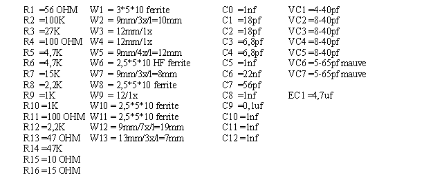
For readable version:
COMPON.GIF
There are some components that need extra attention. Transistors usually have 3
or 4 different
wires comin' out. If you connect these wires in the wrong way the transmitter
won't work. It may even explode. The picture below shows how to prevent from
such an event.
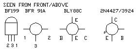
You can find the numbers and letters back in the soldering schematic.
Coils also require extra attention. You can buy the coils trough ferrite in the
shop, but the other ones have to be made yourself. Use 1mm AgCu wire. A coil
like 7x/d=10mm/l=15mm, goes round 7 times, has an diameter of 10 millimeter and
is long 15 millimeters. The best way to make a coil is to bend it around a
pencil or other cilindrical shaped object tight. The diameter of the object is
always d-coil minus 1 mm. In this case 9mm. As I said: bend the wire round (in
this case 7times) with the revolves tight together. To get the desired length
stretch the coil when still around the pencil
If you decide to build the transmitter and buy the parts, this list will be
handy:
COMPON.DOC
READ THIS E-MAIL I RECEIVED
erwin.huybreghts@verhaert.com
Hello,
just to give some input: I have built the 15W FM transmitter you describe about
4.5 years ago.
The PCB lay out and component selection is still the same as it was then and
after some modifications, I had an average output power of 16.8W @ 98.6 MHz (measured
with Rhode and Schwarz equipement). You will need additional filtering on the
power lines otherwise a stable power supply for the modulating circuit cannot be
guaranteed. The legs of the modulating diode are, at best, kept long for extra
capacitance. This to make sure you fall within the FM band because before I did
that, I had
problems falling withing the 88-108 MHz. I was actually interfering with the
police and fire brigade radio bands (Belgium). Of course, this is not the
intention. I also advice you and readers to carefully check the orientation of
the BLY88 because my professor blew one up due to lack of specification and
inclarities in the datasheets (the actual pin out of the component changed a few
years ago, resulting in a swapped emitter and collector - no good if you
position it wrong!!! (the white cap flies of)). You will also need to play with
the spacing between the windings of the different coils in order to get a good
coupling between the different stages. I short circuited parts of the coils and
made them smaller than specified to have near-optimal coupling. I also added
extra ferrite bead coils for extra decoupling of the power lines, and used a
very good shielding. Above 16.8W there is coupling (primarily through the air)
between the output and the modulating/input stage and oscillation occurs. So for
I have not found any other solution than lower the output power. Both extra
decoupling
and extra shielding had no effect (my transmitter is built into a fully closed
aluminium box with seperating plates that are fully connected to the case or
ground plane on the PCB, except from where tracks run (0.5mm spacing provided)).
Also, use a good heat sink for the last power stage!!!
I hope this information will be usefull. If you have any questions, please ask.
Kind regards,
Erwin
Erwin Huybreghts
Electronic Engineer
Space applications and space instruments division
Verhaert D&D
Hogenakkerhoekstraat 9
9150 Kruibeke
Belgium
Tel.: +32 (0) 3/250.14.50
Fax.: +32 (0) 3/253.14.64
Title: 15W Fm-transmitter
electronic circuit
Source: www.geocities.com/SouthBeach/3433/transmit.htm
Published on: 2005-02-03
Reads: 4692
Print version: ![]()
Other electronic circuits and schematics from RF circuit
-
Active Antenna for Medium Wave
-
4 Transistor Transmitter
-
Band 2 Preamplifier
-
3W FM Transmitter
-
FM voice transmitter for Band 2 VHF
-
Surveillance Transmitter Detector
-
SW RF Pre-Amplifier
-
Simple FM Transmitter
-
60W Linear amplifier
-
Economy short-wave receiver
