Transmitter FM 45W with valve
TECHNICAL CHARACTERISTICS:
Tendency of catering: 220V AC
Frequency of emission at FM: 88~108MHz
Force of expense: max 45W (without the R3),
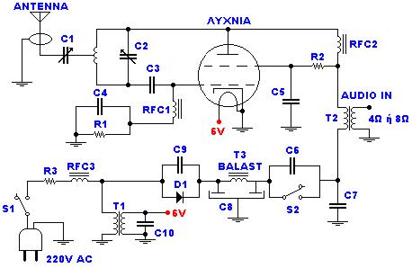
Materially:
| R1 | 15KW/2W |
| R2 | 1KW/10W |
| R3 | 1KW/10W (for biggest force in the exit you replace with short-circuit). |
| C1 | 50pF trimmer |
| C2 | 30pF trimmer |
| C3 | 22pF/4KV |
| C4, c6, c9 | 10nF/1KV |
| C5, c7 | 1nF/1KV |
| C8 | 100mF+100mF/450V (Double electrolytic) |
| C9, c10 | 10nF |
| RFC1, rfc2, rfc3 | air Inductors: 15 coils diameter 8mm, from wire 1mm. |
| T1 | Transformer 220V/6V-1A |
| T2 | Transformer of configuration with being first 4 or 8W |
| T3 | Inductor with core ferrite (externally it resembles with small transformer but has a turn only). |
| D1 | BY127 rectifier |
| Lamp | 807 SYLV USA or EL34 or equivalent |
| ANTENNA | Simple dipole L/2. (L= wave length) |
| S1 | Main switch of catering. |
| S2 | Switch of catering of rise (him we close after zestacej' the thread). |
Most elements you can him find in a old back-white television with lamps.
Regulations:
With the C2 we regulate the frequency.
With the C1 we adapt the resistance of aerial (practically him we regulate so that it is heard our voice in the radio as long as you become cleaner).
Notes:
The catering better it does not become at straight line from the network 220V but via transformer 220V/220V of isolation and safety 1A.
When does not exist the R3, the force of expense is bigger, but respectively is increased also the hum 50Hz, because the simplicity of designing.
The control (Audio In) can become from a kasseto'fwno or other powerful source. If it is microphone it will be supposed precedes amplifier so that it acquires a force of order of 8W roughly.
Title: Transmitter FM 45W with valve
electronic circuit
Source: www.electronics-lab.com
Published on: 2005-02-03
Reads: 1700
Print version: ![]()
Other electronic circuits and schematics from RF circuit
-
Surveillance Transmitter Detector
-
Video to RF Modulator
-
CB transmitter
-
FM radio
-
FM Transmitter Bug
-
Small Radio Transmitter
-
FM Transmitter with Opamp
-
A small FM transmitter (SMD)
-
60W Linear amplifier
-
CB receiver