FM transmitter
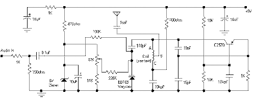
Colpitts oscillator. Its frequency depends on the capacitance of the vary cap diode. The center frequency is changed by varying the biasing voltage of the vary cap through the 47K pot. You can use a 75cm telescopic antenna or simply a length of hook-up wire. Mine worked fine with a 6cm hook-up wire and gave a range of 100m with a good FM receiver. The approx. cost of the circuit is around Rs.35
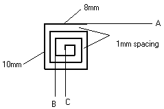
Coil Details (Print on the PCB itself)
The coil shown below can be constructed on the PCB itself as PCB track. Just
transfer the dimensions on a copper board and etch it. If the 1mm spacing is
difficult use a sharp blade to remove unwanted copper.
You can also use a copper wire and construct a square spiral of the dimensions
shown below. Please note that a small deviation from the given dimensions is
permissible.
Note: You can even try a coil made of 18SWG copper wire of 5 turns and 5mm dia
with air core. The center tap can then be taken at the 2nd or 3rd turn.( I
have'nt tried it tell me if it works well)

Title: FM transmitter
electronic circuit
Source: www.electronic-circuits-diagrams.com
Published on: 2005-02-09
Reads: 2801
Print version: ![]()
Other electronic circuits and schematics from RF circuit
-
Economy short-wave receiver
-
4 Watt FM Transmitter
-
Sensitive Field Strength Meter
-
3W FM Transmitter
-
Electronic Eavesdropping Devices Detector
-
Low-Frequency Crystal Controlled Oscillator
-
Medium range transmitter
-
FM Transmitter with Opamp
-
MPF102 FM Receiver
-
VHF Video Transmitter

