
Control electrical appliances using PC
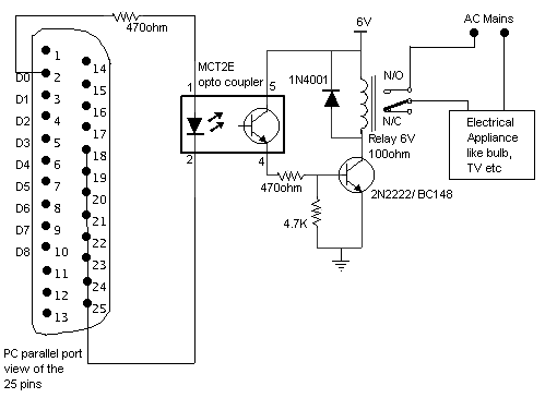
Here is a circuit for using the printer port of a PC, for control application
using software and some interface hardware. The interface circuit along with the
given software can be used with the printer port of any PC for controlling up to
eight equipment .
The interface circuit shown in the figure is drawn for only one device, being
controlled by D0 bit at pin 2 of the 25-pin parallel port. Identical circuits
for the remaining data bits D1 through D7 (available at pins 3 through 9) have
to be similarly wired. The use of opto-coupler ensures complete isolation of the
PC from the relay driver circuitry.
Lots of ways to control the hardware can be implemented using software. In C/C++
one can use the outportb(portno,value) function where portno is the parallel
port address (usually 378hex for LPT1) and 'value' is the data that is to be
sent to the port. For a value=0 all the outputs (D0-D7) are off. For value=1 D0
is ON, value=2 D1 is ON, value=4, D2 is ON and so on. eg. If value=29(decimal)
= 00011101(binary) ->D0,D2,D3,D4 are ON and the rest are OFF.
Click here for the sample software.
Click here for the source code of the software (in C).
Title: Control electrical appliances using PC
electronic circuit
Source: www.electronic-circuits-diagrams.com
Published on: 2005-02-01
Reads: 3004
Print version: 
Other electronic circuits and schematics from PC related
-
IrDA interface for your mainboard
-
A Laboratory Control System for Cold Atom Experiments
-
Monitor Your PC's CPU Core Temperature
-
LCD2LPT with LIRC
-
3-Axis Stepper Controller
-
Parallel Port Relay Interface
-
DS1621 pc thermometer
-
RS-232 Laser Transceiver
-
VGA to TV Scart
-
The Simplified I/O Interface