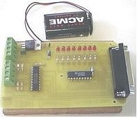
The Simplified I/O Interface
This was the first of the interface boards developed in conjunction with members of the Educational Computing Association of Western Australia (ECAWA). This board follows on from the "Simplified Output Interface". We wanted to be able to experiment with the input lines using a battery powered interface. Everything has been compacted to keep the board costs to a minimum.
You can use a nine volt battery for normal use. (The diode connected to the negative terminal will protect the 7805 voltage regulator against reverse polarity.) If you want to try driving stepper motors you will need to use a 12 volt supply able to deliver at least one amp. The supply should be regulated!!
If you wanted to, you could connect a small DC electric ("hobby") motor directly across an output line. As long as the total current drawn through the ULN2803 was less than one amp you should have no problems.
For sample Visual Basic Code see: http://www.southwest.com.au/~jfuller/vb/vbout.htm
For further information on interfacing, download the booklet at: http://www.southwest.com.au/~jfuller/robot3.zip
 Component Overlay |
 The Simplified I/O Interface |
PCB Artwork for the Simplified I/O Interface.
(Permission is granted for the download, duplication and non-commercial use of
this image.)
Schematic of the ULN2803 Integrated Circuit showing detail for one driver line.
Parts List
8 x 3mm LEDs
8 x 390 ohm 1/4 watt resistors
4 x 100 kohm 1/4 watt resistors
1 x 10 kohm 1/4 watt resistor
1 x 1N4001 Diode
1 x 7805 voltage regulator
1 x 0.01 uF greencap capacitor
1 x ULN 2803
1 x 74LS244
1 x 15 volt zener diode
1 x PCB mount, right angled DB25 socket
1 x PCB
1 x 9 volt battery clip
1 x 25 pin male to male cable
1 x 9 volt battery
Optional: 9 x 2-way PCB Mount Screw Terminals
(When working with stepper motors you will need the solder on some PCB Mount
Screw Terminals for prototyping purposes. Once you have the motor wiring worked
out it would be best to solder stepper motor wires directly to the board.)
Title: The Simplified I/O Interface
electronic circuit
Source: www.southwest.com.au/~jfuller
Published on: 2005-02-03
Reads: 1441
Print version: ![]()
Other electronic circuits and schematics from PC related
-
7 segment rolling display using PC
-
PC Serial Receiver (57.6K Baud / TTL & CMOS)
-
Simple PC thermometer
-
VGA to TV Scart
-
Opto-Isolated Stepper Motor Controller
-
Reading Data From The Parallel Port
-
RJ45 Network card to IR communication
-
Improved Infrared Receiver with status led
-
DS1620 based USB Digital Thermometer
-
RS-232 Laser Transceiver