VGA to TV Scart
THE CIRCUIT
Note : this circuit is auto translated from the Greek version
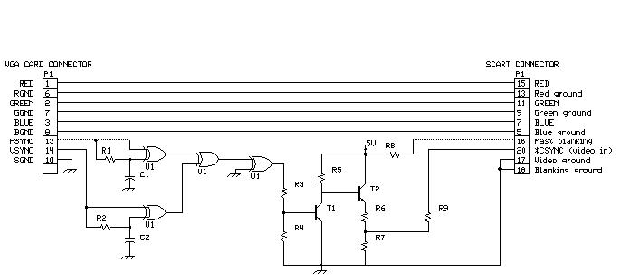
This is a circuit converter from VGA in TV SCART connection. Basically it is a circuit that accepts the signals from the exit of card VGA, him it then changes in combination RGB+composite sync and it leads to fastener SCART. The elements of picture from her exit card VGA, RED, BLUE and GREEN are already ready, bring right tendency the 0.the 7 vpp and right resistance of 75W for direct connection with fastener SCART, for depiction in the TV. What should it changes it is the right combination the horizontal and vertical synchronization signals from the VGA in a complex signal that will be led to the entry VIDEO in pin SCART. This transformation him they undertake electronic elements of circuit.
THAT IT FUNCTIONS
This circuit has been drawn in order to it changes regular signals VGA, standard RGB and the complex signal of timing. circuit is simple because signal RGB from the VGA is ready in standart level 0,7 Vpp and in 75W charge. For the signals of timing exists a circuit that changes the horizontal and vertical in complex. The circuit is simple based on a TTL completed with four gates XOR, two resistances and two capacitors. His choice completed TTL it is reasonable because the signals of timing of VGA they are signals TTL. The converter of signals of timing is system that regulates the difference of polarity of signals, so complex signal it is always right. Card VGA uses different polarities in the signals of timing in order to it informs the Monitor anymore analysis it uses. This circuit regulates the changes polarity the signals in least from 200 mSec, that are faster and from the time of regulation of common Monitor VGA. The circuit in order to function need stabilized tendency + 5V (+/- 5%) and current 120mA.
MANUFACTURE
Converter VGA in TV is easy in the manufacture to him it is enough exists a relative experience in the manufactures electronic. The circuit can be manufactured on one small EPOXY board. Remember only to connect also the completed circuit with the catering of 5V (in the drawing it does not appear). The circuit in order to it rightly functions it needs without fail stabilized tendency consequently it should you use also a REGULATOR LM7805. In the entry the 7805 the tendency should be from 9 until 16V so that it accomplishes us it gives the desirable stabilized tendency of 5V in his exit. Tendency from 9 until 16V we can him take also from our computer or from exterior small power supply's socket. From the computer we can we take from the following points: from door RS232, from the parallel door , from the PS2 and finally from a gambling chip of catering by his interior computer. Big attention should be given in him you stick that you will make and in the wiring of circuit, you avoid the chills you stick why the circuit functions in big frequency and sure will be created instabilities in the circuit with result bad quality of picture or even lack timing in the screen of TV. Be careful in order that the soldering is clean and glazing thus you will only be sure that the soldering has become right. For the wiring you are used shielded cables blentaz and ground the thorax of cables in the board's chassis. Good it is manufacture it is placed in a plastic box and it is placed and a connector EURO/scart female for placement in chassis.
Good success.
MATERIALLY
Title: VGA to TV Scart
electronic circuit
Source: www.electronics-lab.com
Published on: 2005-02-03
Reads: 2033
Print version: ![]()
Other electronic circuits and schematics from PC related
-
Stepper motor controller
-
Reading Data From The Parallel Port
-
The Simplified I/O Interface
-
DS1621 pc thermometer
-
Monitor Your PC's CPU Core Temperature
-
LCD Module Control with PC
-
The Relay Sub Board
-
3-Axis Stepper Controller
-
An Improved Infrared Receiver with Status LED
-
PC Serial Receiver (57.6K Baud / TTL & CMOS)