Black Light
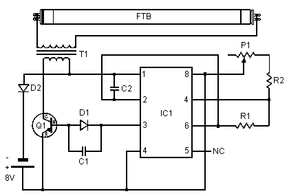
This circuit is a simple ultraviolate light that can be powered by a 6 volt battery or power supply that is capable of supplying 1 or more amps.

Theoritical Diagramm
|
|
|
PARTS
| Part | Total Qty. | Description |
| C1 | 1 | 0.0047uf Mono Capacitor |
| C2 | 1 | 0.1uf Disc Capacitor |
| D1, D2 | 2 | 1N4007 Diode |
| FTB | 1 | Filtered Blacklight Tube |
| IC1 | 1 | 555 Timer IC |
| P1 | 1 | 10k Trim Pot |
| Q1 | 1 | TIP30 PNP Power Transistor |
| R1 | 1 | 470 Ohm Resistor |
| R2 | 1 | 270 Ohm Resistor |
| T1 | 1 | Medium Yellow Inverter Transformer |
| MISC | 1 | IC Socket, Heat Sink For Q1, Screw, Nut, Wire and PC Board |
Notes:
1. P1 changes brightness of the black light tube.
Title: Black Light
electronic circuit
Source: www.electronics-lab.com
Published on: 2005-02-03
Reads: 1105
Print version: ![]()
Other electronic circuits and schematics from Motor, light and power control
-
Christmas Star
-
Automatic Room Lights
-
Simple DC motor PWN speed control
-
Fancontrol
-
Auto Heat Limiter for Soldering Iron
-
Temperature-controlled Fan
-
DC Motor Reversing Circuit
-
Solid State Power Controller
-
Optical toggle switch using a single Chip
-
Dark-activated LED or Lamp Flasher


