Simple IF Signal Generator
Here is a versatile circuit of IF signal generator which may be of interest
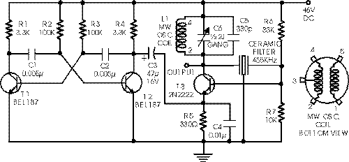
to radio hobbyists and professionals alike.Transistors T1 and T2 form an astable
multivibrator oscillating in the audio frequency range of 1 to 2 kHz. RF
oscillator is built around transistor T3. Here again a 455kHz ceramic filter/resonator
is employed for obtaining stable IF. The AF from multivibrator is coupled from
collector of transistor T2 to emitter of transistor T3 through capacitor C3. The
tank circuit at collector of transistor T3 is formed using medium wave
oscillator coil of transistor radio, a fixed 100pF capacitor C5 and half section
of a gang capacitor (C6).
The oscillator section may be easily modified for any other intermediate
frequency by using ceramic filter or resonator of that frequency and by making
appropriate changes in the tank circuit at collector of transistor T3. Slight
adjustment of bias can be affected by varying values of resistors R6 and R7, if
required.
Title: Simple IF Signal Generator
electronic circuit
Source: www.electronic-circuits-diagrams.com
Published on: 2005-02-01
Reads: 2429
Print version: ![]()
Other electronic circuits and schematics from Oscillators and timers
-
50 Hertz LED Clock Timebase
-
28 LED Clock Timer
-
Bedside Lamp Timer
-
Pulse-Generator & Signal-Tracer
-
Timed Beeper
-
Triangle and Squarewave Generator
-
Mini Metronome
-
Precision Metronome and Pitch generator
-
Amplifier Timer
-
Photo Timer Circuit

