100W Guitar Amplifier
PART I
Introduction
Guitar amplifiers are always an interesting challenge. The tone controls, gain and overload characteristics are very individual, and the ideal combination varies from one guitarist to the next, and from one guitar to the next. There is no amp that satisfies everyone's requirements, and this offering is not expected to be an exception.
One major difference however, is that if you build it yourself, you can modify things to suit your own needs, the ability to experiment is the key to this circuit, which is although presented in complete form, there is every expectation that builders will make modifications to suit themselves.
The amp is rated at 100W into a 4 Ohms load, as this is typical of a "combo" type amp with two 8 Ohm speakers in parallel. Alternatively, you can run the amp into a "quad" box (4 x 8 Ohm speakers in series parallel - see Figure 5 in Project 27b, the original article) and will get about 60 Watts. For the really adventurous, 2 quad boxes and the amp head will provide 100W, but will be much louder than the twin. This is a common combination for guitarists, but it does make it hard for the sound guy to bring everything else up to the same level.
Note: This is a fully revised version of the original 100W guitar amp, and although there are a great many similarities, there are some substantial differences - so much so that a new version was warranted. This is (in part) because PCBs are now available for both the power and preamps. The update was sufficiently substantial to warrant retaining the original version, which is still available as Project 27b.
The Pre-Amplifier
The preamp circuit is shown in Figure 1, and has a few interesting characteristics that separate it from the "normal" - assuming that there is such a thing. This is simple but elegant design, that provides excellent tonal range. The gain structure is designed to provide a huge amount of gain, which is ideal for those guitarists who like to get that fully distorted "fat" sound.
However, with a couple of simple changes, the preamp can be tamed to suit just about any style of playing. Likewise, the tone controls as shown have sufficient range to cover almost anything from an electrified violin to a bass guitar - The response can be limited if you wish (by experimenting with the tone control capacitor values), but I suggest that you try it "as is" before making any changes. (See below for more info.)
Figure 1 - Guitar Pre-Amplifier
From Figure 1, you can see that the preamp uses a dual opamp as its only amplification.
The lone transistor is an emitter follower, and maintains a low output impedance
after the master volume control. As shown, with a typical guitar input, it is possible
to get a very fat overdrive sound by winding up the volume, and then setting the
master for a suitable level. The overall frequency response is deliberately limited
to prevent extreme low-end waffle, and to cut the extreme highs to help reduce noise
and to limit the response to the normal requirements for guitar. If you use the
TL072 opamp as shown, you may find that noise is a problem - especially at high
gain with lots of treble boost. I strongly suggest that you use an OPA2134 - a premium
audio opamp from Texas Instruments (Burr-Brown division), you will then find this
quite possibly the quietest guitar amp you have ever heard (or not heard :-). At
any gain setting, there is more pickup noise from my guitar than circuit noise -
and for the prototype I used carbon resistors!
 |
Notes:
|
The power supply section (bottom left corner) connects directly to the main +/-35V power amp supply. Use 1 Watt zener diodes (D5 and D6), and make sure that the zener supply resistors (R18 and R19, 680 ohm 1 Watt) are kept away from other components, as they will get quite warm in operation. Again, the preamp PCB accommodates the supply on the board.
The pin connections shown (either large dots or "port" symbols) are the pins from the PCB. Normally, all pots would be PCB types, and mounted directly to the board. For a DIY project, that would limit the layout to that imposed by the board, so all connections use wiring. It may look a bit hard, but is quite simple and looks fine when the unit is completed. Cable ties keep the wiring neat, and only a single connection to the GND point should be used (several are provided, so choose one that suits your layout. VCC is +35V from the main supply, and VEE is the -35V supply.
If you don't need all the gain that is available, simply increase the value of R6 (the first 4k7 resistor) - for even less noise and gain, increase R11 (the second 4k7) as well. For more gain, decrease R11 - I suggest a minimum of 2k2 here.
If the bright switch is too bright (too much treble), increase the 1k resistor (R5) to tame it down again. Reduce the value to get more bite. The tone control arrangement shown will give zero output if all controls are set to minimum - this is unlikely to be a common requirement in use, but be aware of it when testing.
The diode network at the output is designed to allow the preamp to generate a "soft" clipping characteristic when the volume is turned up. Because of the diode clipping, the power amp needs to have an input sensitivity of about 750mV for full output, otherwise it will not be possible to get full power even with the Master gain control at the maximum setting.
Make sure that the input connectors are isolated from the chassis. The earth isolation components in the power supply help to prevent hum (especially when the amp is connected to other mains powered equipment).
If problems are encountered with this circuit, then you have made a wiring mistake ... period. A golden rule here is to check the wiring, then keep on checking it until you find the error, since I can assure you that if it does not work properly there is at least one mistake, and probably more.
The input, effects and output connections are shown in Figure 1B.
- Input - these are quite the opposite of what you might think. The same basic idea is used on Fender amps, as well as nearly all others that have dual inputs for a channel. The Hi input is used for normal (relatively low output) guitar pickups, and is "Hi" gain. "Lo" in this design has about 14 dB less gain, and is intended for high output pickups so the first amplifier stage does not distort. The switching jack on the Hi input means that when a guitar is connected to the Lo input, it forms a voltage divider because the other input is shorted to earth.
- Effects - Preamp out and power amp in connections allow you to insert effects, such as compression (for really cool sustain, that keeps notes just hanging there), reverb, digital effects units, etc. The preamp out is wired so that the preamp signal can be extracted without disconnecting the power amp, so can be used as a direct feed to the mixer if desired. This is especially useful for bass. The preamp output can also be used to slave another power amplifier (as if you need even more - you do for bass, but not guitar).
- Output - A pair of output connectors is always handy, so that you can use two speaker boxes (don't go below 4 ohms though), or one can be used for a speaker level DI box. Because of the high impedance output stage, headphones cannot (and must not!) be connected to the speaker outputs. The 'phones will be damaged at the very least, but (and much, much worse) you could easily cause instant permanent hearing loss.
Figure 1B - Internal Wiring
The connections shown are very similar (ok, virtually identical :-) to those used in my prototype. Noise is extremely low, and probably could have been lower if I had made the amp a little bigger. All connectors must be fully insulated types, so there is no connection to chassis. This is very important !
You will see from the above diagram that I did not include the "loop breaker" circuit shown in the power supply diagram. For my needs, it is not required, for your needs, I shall let you decide. If you choose to use it, then the earth (chassis) connection marked * (next to the input connectors) must be left off.
A few important points ...
- The main zero volt point is the connection between the filter caps. This is the reference for all zero volt returns, including the 0.1 ohm speaker feedback resistor. Do not connect the feedback resistor directly to the amp's GND point, or you will create distortion and possible instability.
- The supply for the amp and preamp must be taken directly from the filter caps - the diagram above is literal - that means that you follow the path of the wiring as shown.
- Although mentioned above, you might well ask why the pots don't mount directly to the PCB to save wiring. Simple really. Had I done it that way, you would have to use the same type pots as I designed for, and the panel layout would have to be the same too, with exactly the same spacings. I figured that this would be too limiting, so wiring it is. The wiring actually doesn't take long and is quite simple to do, so is not a problem.
- I did not include the "Bright" switch in Figure 1B for clarity. I expect that it will cause few problems.
Bass Guitar, Electric Piano
As shown, the preamp is just as usable for bass or electric piano as for rhythm or lead guitar. A couple of changes that you may consider are ...
- Delete the clipping diodes (unless fuzz bass/piano is something you want,
of course). If these are removed, then the output should be taken directly from
the Master output pin (M-OUT in Figure 1), so leave out / change the following
...
- Delete R14, and D1-D4
- Delete Q1 and associated components (C14, C15, R15, R16, R17)
- Delete VR5
- Change R13 from 4.7k to 100 ohms
Power Amplifier
The power amp (like the previous version) is loosely based on the 60 Watt amp previously published (Project 03), but it has increased gain to match the preamp. Other modifications include the short circuit protection - the two little groups of components next to the bias diodes (D2 and D3). This new version is not massively different from the original, but has adjustable bias, and is designed to provide a "constant current" (i.e. high impedance) output to the speakers - this is achieved using R23 and R26. Note that with this arrangement, the gain will change depending on the load impedance, with lower impedances giving lower power amp gain. This is not a problem, so may safely be ignored.
Should the output be shorted, the constant current output characteristic will provide an initial level of protection, but is not completely foolproof. The short circuit protection will limit the output current to a relatively safe level, but a sustained short will cause the output transistors to fail if the amp is driven hard. The protection is designed not to operate under normal conditions, but will limit the peak output current to about 8.5 Amps. Under these conditions, the internal fuses (or the output transistors) will probably blow if the short is not detected in time.
Figure 2 - Power Amplifier
Figure 2 shows the power amp PCB components - except for R26 which does not mount on the board. See Figure 1B to see where this should be physically mounted. The bias current is adjustable, and should be set for about 25mA quiescent current (more on this later). The recommendation for power transistors has been changed to higher power devices. This will give improved reliability under sustained heavy usage.
|
|
As shown, the power transistors will have an easy time driving any load down to 4 ohms. If you don't use the PCB (or are happy to mount power transistors off the board), you can use TO3 transistors for the output stage. MJ15003/4 transistors are very high power, and will run cooler because of the TO-3 casing (lower thermal resistance). Beware of counterfeits though! There are many other high power transistors that can be used, and the amp is quite tolerant of substitutes (as long as their ratings are at least equal to the devices shown). The PCB can accommodate Toshiba or Motorola 150W flat-pack power transistors with relative ease - if you wanted to go that way. TIP3055/2966 or MJE3055/2955 can also be used for light or ordinary duty. |
At the input end (as shown in Figure 1B), there is provision for an auxiliary output, and an input. The latter is switched by the jack, so you can use the "Out" and "In" connections for an external effects unit. Alternatively, the input jack can be used to connect an external preamp to the power amp, disconnecting the preamp.
The speaker connections allow up to two 8 Ohm speaker cabinets (giving 4 Ohms). Do not use less than 4 ohm loads on this amplifier - it is not designed for it, and will not give reliable service!
All the low value (i.e. 0.1 and 0.22 ohm) resistors must be rated at 5W. The two 0.22 ohm resistors will get quite warm, so mount them away from other components. Needless to say, I recommend using the PCB, as this has been designed for optimum performance, and the amp gives a very good account of itself. So good in fact, that it can also be used as a hi-fi amp, and it sounds excellent. If you were to use the amp for hi-fi, the bias current should be increased to 50mA. Ideally, you would use better (faster / more linear) output transistors as well, but even with those specified the amp performs very well indeed. This is largely because they are run at relatively low power, and the severe non-linearity effects one would expect with only two transistors do not occur because of the parallel output stage.
Make sure that the bias transistor is attached to one of the drivers (the PCB is laid out to make this easy to do). A small quantity of heatsink compound and a cable tie will do the job well. The diodes are there to protect the amp from catastrophic failure should the bias servo be incorrectly wired (or set for maximum current). All diodes should be 1N4001 (or 1N400? - anything in the 1N400x range is fine). A heatsink is not needed for any of the driver transistors.
The life of a guitar amp is a hard one, and I suggest that you use the largest heatsink you can afford, since it is very common to have elevated temperatures on stage (mainly due to all the lighting), and this reduces the safety margin that normally applies for domestic equipment. The heatsink should be rated at 0.5В° C/Watt to allow for worst case long term operation at up to 40В°C (this is not uncommon on stage).
Make sure that the speaker connectors are isolated from the chassis, to keep the integrity of the earth isolation components in the power supply, and to ensure that the high impedance output is maintained.
Power Supply
WARNING - Do not attempt construction of the power supply if you do not know how to wire mains equipment.
The power supply is again nice and simple, and does not even use traditional regulators for the preamp (details are on the preamp schematic in Figure 1). The power transformer should be a toroidal for best performance, but a convention tranny will do just fine if you cannot get the toroidal.
|
|
Do not use a higher voltage than shown - the amplifier is designed for a maximum loaded supply voltage of +/-35V, and this must not be exceeded. Normal tolerance for mains variations is +/-10%, and this is allowed for. The transformer must be rated for a nominal 25-0-25 volt output, and no more. Less is Ok if the full 100W is not needed. |
Figure 3 - Power Supply
The transformer rating should be 150VA (3A) minimum - there is no maximum, but the larger sizes start to get seriously expensive. Anything over 250VA is overkill, and will provide no benefit. The slow-blow fuse is needed if a toroidal transformer is used, because these have a much higher "inrush" current at power-on than a conventional transformer. Note that the 2 Amp rating is for operation from 220 to 240 Volt mains and as shown is suitable for a 200VA transformer - you will need an 4 or 5 Amp fuse here for operation at 115 Volts. Smaller transformers can use a smaller fuse - I am using a 2A slow blow fuse in my prototype (160VA transformer at 240V mains input), which seems to be fine - it allows for a maximum load of 480VA which will never be achieved except under fault conditions.
Use good quality electrolytics (50V rating, preferably 105В°C types), since they will also be subjected to the higher than normal temperatures of stage work. The bridge rectifier should be a 35 Amp chassis mount type (mounted on the chassis with thermal compound).
The earth isolation components are designed to prevent hum from interconnected equipment, and provide safety for the guitarist (did I just hear 3,000 drummers asking "Why ??"). The 10 Ohm resistor stops any earth loop problems (the major cause of hum), and the 100nF capacitor bypasses radio frequencies. The bridge rectifier should be rated at least 5A, and is designed to conduct fault currents. Should a major fault occur (such as the transformer breaking down between primary and secondary), the internal diodes will become short circuited (due to the overload). This type of fault is extremely rare, but it is better to be prepared than not.
Another alternative is to use a pair of high current diodes in parallel (but facing in opposite directions). This will work well, but will probably cost as much (or even more) than the bridge.
All fuses should be as specified - do not be tempted to use a higher rating (e.g. aluminium foil, a nail, or anything else that is not a fuse). Don't laugh, I have seen all of the above used in desperation. The result is that far more damage is done to the equipment than should have been the case, and there is always the added risk of electrocution, fire, or both.
Electrical Safety
Once mains wiring is completed, use heatshrink tubing to ensure that all connections
are insulated. Exposed mains wiring is hazardous to your health, and can reduce
life expectancy to a matter of a few seconds !
Also, make sure that the mains lead is securely fastened, in a manner acceptable to local regulations. Ensure that the earth lead is longer than the active and neutral, and has some slack. This guarantees that it will be the last lead to break should the mains lead become detached from its restraint. Better still, use an IEC mains connector and a standard IEC mains lead. These are available with integral filters, and in some cases a fuse as well. A detachable mains lead is always more convenient than a fixed type (until your "roadie" loses the lead, of course. You will never do such a thing yourself :-)
The mains earth connection should use a separate bolt (do not use a component mounting bolt or screw), and must be very secure. Use washers, a lock washer and two nuts (the second is a locknut) to stop vibration from loosening the connection.
Testing
If you do not have a dual output bench power supply
Before power is first applied, temporarily install 22 Ohm 5W wirewound "safety"
resistors in place of the fuses. Do not connect the load at this time! When power
is applied, check that the DC voltage at the output is less than 1V, and measure
each supply rail. They may be slightly different, but both should be no less than
about 20V. If widely different from the above, check all transistors for heating
- if any device is hot, turn off the power immediately, then correct the mistake.
If you do have a suitable bench supply
This is much easier! Do not connect a load at this time. Slowly advance the voltage
until you have about +/-20V, watching the supply current. If current suddenly starts
to climb rapidly, and voltage stops increasing then something is wrong, otherwise
continue with testing. (Note: as the supply voltage is increased, the output voltage
will fluctuate initially, then drop to near 0V at a supply voltage of about +/-15V
or so. This is normal.)
Once all is well, connect a speaker load and signal source (still with the safety resistors installed), and check that suitable noises (such as music or tone) issue forth - keep the volume low, or the amp will distort badly with the resistors still there if you try to get too much power out of it.
If the amp has passed these tests, remove the safety resistors and re-install the fuses. Disconnect the speaker load, and turn the amp back on. Verify that the DC voltage at the speaker terminal does not exceed 100mV, and perform another "heat test" on all transistors and resistors.
When you are satisfied that all is well, set the bias current. Connect a multimeter between the collectors of Q10 and Q11 - you are measuring the voltage drop across the two 0.22 ohm resistors (R20 and R21). The desired quiescent current is 25mA, so the voltage you measure across the resistors should be set to 11mV +/-2mV. The setting is not overly critical, but at lower currents, there is less dissipation in the output transistors. Current is approximately 2.2mA / mV, so 10mV (for example) will be 22mA.
After the current is set, allow the amp to warm up, and readjust the bias when the temperature stabilises. This may need to be re-checked a couple of times, as the temperature and quiescent current are slightly interdependent. When you are happy with the bias setting, you may seal the trimpot with a dab of nail polish.
PART II
IntroductionThe Project 27 article showed the schematics and wiring of the 100W guitar amp. Here are some pictures of the prototype, so you can see what the various bits look like. Just as a refresher, the internal wiring diagram is shown - you will be able to see how this all goes together in the photos.
Figure 1B - Internal Wiring
The connections shown are virtually identical to those used in my prototype. Noise is extremely low, and probably could have been lower if I had made the amp a little bigger. All connectors must be fully insulated types, so there is no connection to chassis. This is very important !
The photos below give you some idea what the final unit looks like. Mine is really small, but I suggest that you make yours bigger. The one I made will never have to put up with life on the road, so the metalwork (and cabinet) are cobbled together with whatever I could find in my workshop. It's still very sturdy, but I know from experience just how sturdy a "live performance" amp needs to be. If it will be damaged by 120kg of other gear sitting on top of it, in a truck, and on a bumpy road (all at the same time), then it probably won't survive.
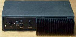
Make sure that your cabinet does not interfere with air flow around the heatsink.
Leaving it sticking out the back (as I did) is probably not ideal, but it must get
proper ventilation. The heatsink does not need to be as big as the one I used,
but since there is no such thing as a heatsink that is too big, make sure you don't
skimp on this very important component.
 |
 |
 |
 |
Click on an image to see the full size view |
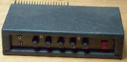
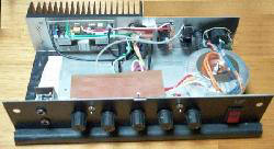
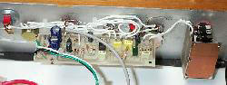
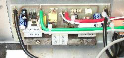
In order from the top left, you can see the front view,
rear view and an internal view. Note the shield above the preamp.
The preamp (with the shield removed) and power amp are shown in more detail to the left. |
The photos of the outside are not as clear as they could be - black on black is always a pain to get good resolution - being in a hurry may have had something to do with it as well.
Note the shielding for the preamp. Shield the inputs with sheet metal or some scrap unetched PCB material, and a similar shield over the preamp helps prevent noise pickup. These are important for lowest noise level and to ensure stability. The preamp has an enormous amount of gain, and internal feedback is highly undesirable. Make certain that the shield does not create a hum loop! If you use PCB material, it can be held in place with pieces of tinned copper wire joined to the ground bus for the pots. Only one point of the shield should be in electrical contact with the bus - I used an engraving tool to make a separate copper "land" for the second (mechanical only) connection.
The power amp mounts using a couple of pieces of steel as clamps for the transistors. No other mounting is needed, and the amp is extremely solidly mounted by this method. The only steel stock I had on hand was rusty - you can see the pitting in the image. This does not affect anything, but it does look a little grotty (again, I was in a hurry :-)
Note that the PCBs you see in the photos are the prototypes. The final boards are similar, but do look slightly different, as I changed some of the locations and made some other mods (these are incorporated in the prototypes by cut tracks and jumpers).
For those who may not wish to build the amp and preamp boards, fully built and tested modules will be available shortly (PCBs only - excludes hardware, pots, jacks, heatsink and power supply). These will be supplied with sufficient documentation to make final wiring and assembly a breeze.
The entire amp as you see it here was built (and documented) in two weekends (allowing time for mowing and other similarly exciting activities), so it can hardly be considered an arduous task to build one. The case was made from MDF (in this instance Melamine coated, but only because I have a whole pile of the stuff :-). The vinyl is stuck on with PVA wood glue, but (again for longevity and strength) I suggest that you use contact adhesive - the staples that you can see on the inside were to make sure that it didn't move while I did the next bit. If you are more patient than I (or if you use contact adhesive), staples are not needed. I would have used speaker carpet, but didn't have enough left.
The actual details of the chassis I leave to the reader - I certainly don't recommend the method I used. One relatively simple way to do it is to use a 2RU rack case, and install that in an MDF sleeve. The sleeve can be covered with vinyl or carpet - both look good and wear well.
Title: 100W Guitar Amplifier
electronic circuit
Source: http://sound.westhost.com/
Published on: 2005-07-10
Reads: 7654
Print version: ![]()
Other electronic circuits and schematics from Audio
-
3 Channel Spectrum Analyzer
-
Mini-box 2W Amplifier
-
Minimalist Discrete Hi-Fi Preamp
-
100W RMS Amplifier
-
Digital Volume Control
-
Automatic Loudness Control
-
Portable Headphone Amplifier
-
Stereo Channel Selector
-
Sound Pressure Level Meter
-
Baxendall Tone Control