Video monitor adapter enhances oscilloscope
Video signals can be difficult to display on an oscilloscope. Normal trigger circuits in most oscilloscopes have trouble getting a stable trigger from the combined vertical and horizontal sync signals, color burst, and picture signal in a composite video waveform. Even the УTV SyncФ trigger detector available in some low-cost oscilloscopes is inadequate to obtain a stable display.

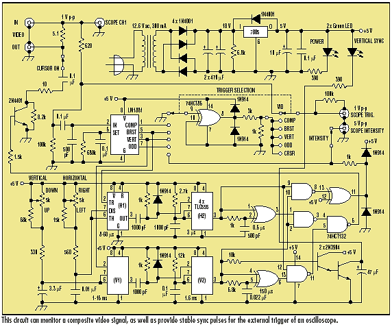
The circuit shown monitors a composite video signal and provides stable sync pulses for the external trigger of an oscilloscope (see the figure). The Trigger Selector switch chooses Video, Composite Sync, Color Burst Sync, Vertical Sync, Vertical Odd Field Sync, or Cursor Position for the oscilloscope. Two timer chains provide a rectangular cursor (width and height approximately 8% of the full screen). The cursor is movable across the full width and height of the screen by adjusting the Horizontal and Vertical Cursor Controls.
The circuit provides a positive Intensity pulse for the oscilloscope Intensity (Z-axis) input. This permits close inspection of any portion of the video signal corresponding to the position of the cursor. If the oscilloscope is hooked up to a color demodulator as a vectorscope, this feature highlights the demodulated color on the vectorscope display. This is useful in applying color correction or enhancement as part of a video-editing setup.
The circuit contains a Power LED and a Vertical Sync Indicator LED. The Cursor On switch allows the movable cursor to be observed on a video monitor attached to the Video Out connector. The Intensity switch controls the Intensity pulse to the oscilloscope.
The LM1881 Sync Detector separates the various sync signals from the composite video into stable logic pulses. Color burst sync, which occurs at the start of every horizontal line, is applied to a 555 CMOS timer. The timer output pulse width is adjusted by the Horizontal Cursor Control over the full width of the line. This output pulse drives a second 555 timer which establishes the cursor window width. The output of this second timer drives a 74HCT86 exclusive-OR gate through an RC circuit, providing a short positive pulse corresponding to the start and end of the horizontal cursor window.
Vertical sync, which occurs at the start of every vertical field, is similarly processed by a parallel set of timer circuits to establish the start and end of the vertical cursor window. The 74HCT132 NAND gates combine these signals into the desired square cursor. The resulting square cursor drives the 2N4401 transistor. When switched on, the transistor reduces the amplitude of the video signal at the Video Out connector through the voltage-divider action of the 5.1-Ω and 10-Ω resistors. This results in a gray cursor surrounding the area of interest on a video monitor. The 0.1-µF capacitor protects the transistor from any dc voltage on the video.
The fixed resistors associated with the Horizontal and Vertical Cursor Controls provide the range of timing adjustments shown. Their values may be modified to account for tolerances of the other components.
Title: Video monitor adapter enhances oscilloscope
electronic circuit
Source: http://www.elecdesign.com
Published on: 2005-06-19
Reads: 2570
Print version: ![]()
Other electronic circuits and schematics from Video and TV
-
Composite color video signal travels on twisted-pair cable
-
Audio / video switch
-
Video Signal Amplifier
-
The Video / Audio Distribution Amplifier
-
Video Line Selector
-
4 Stage 555 Timer for Video Cam Control
-
Video Switch
-
Video multiplexer uses high-speed op amps
-
LH0032 Video Amplifier
-
Video Distributor Amplifier
