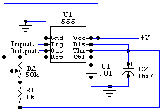
Sound detector latch

Sound detector latch circuit
Parts:
| U1 | NE555 timer IC |
| R1 | 1k resistor |
| R2 | 50k potentiometer |
| C1 | 0.1uF ceramic capacitor |
| C2 | 10uf tantalum capacitor |
All resistors are 5 or 10 percent tolerance, 1/4-watt all capacitors are 10 percent tolerance, rated 35 volts or higher.
When the 555 ic goes into timing mode (triggered by an output signal from the sound detector amplifier,) the timer's output (pin 3) is set into HIGH for a duration set by C2, and R2. adjusting R1 will adjust how long it listens, from 10 seconds all the way down to 2/10ths of a second. this could be used to listen for hand claps.
Title: Sound detector latch
electronic circuit
Source: unknown
Published on: 2012-09-20
Reads: 284
Print version: ![]()
Other electronic circuits and schematics from Audio
-
Improved 3 Transistor Audio Amp (80 milliwatt)
-
100W Guitar Amplifier
-
60W Guitar Amplifier
-
Sound Controlled Filp Flop
-
10 Band Audio Equalizer
-
Sound Level Meter
-
200W audio amplifier
-
250 mW Audio Amplifier
-
Amplified Ear
-
Stereo Channel Selector
