DC to DC Converter
The circuit below is a DC to DC converter using a standard 12 VAC center tapped power transformer wired as a blocking oscillator. The circuit is not very efficient but will produce a high voltage usable for low power applications. The input battery voltage is raised by a factor of 10 across the transformer and further raised by a voltage tripler consisting of three capacitors and diodes connected to the high voltage side of the transformer. The circuit draws about 40 milliamps and should operate for about 200 hours on a couple of 'D' alkaline batteries. Higher voltages can be obtained by reducing the 4.7K bias resistor.
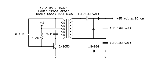
DC to DC Converter circuit
Title: DC to DC Converter
electronic circuit
Source: unknown
Published on: 2007-07-21
Reads: 2108
Print version: ![]()
Other electronic circuits and schematics from Power
-
Fuse Monitor / Alarm
-
Instrument panel lamp dimmer control
-
Over / Under Voltage Cut-Out
-
Nicad Battery Charger
-
Inverter
-
120 VAC Lamp Dimmer
-
High and Low Voltage Cutout with delay and Music
-
TTL Power Supply with ‘Crowbar’ protection
-
LASER Power Supply
-
High Current Power Supply