Phone line indicator
With this circuit you can monitor your telephone line. You are able to detect if any telephone in the same line is busy with the help of a LED. This circuit does not affect the telephone's line provider, so it's trouble free but you use it at your own risk.
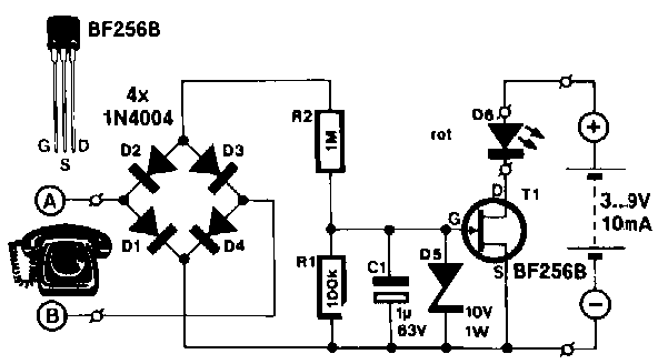
It connects in parallel with the telephone line. The bridge rectifier (D1...D4) at the input protects the circuit from reverse polarity. When none of the telephones of this line is used then the voltage across the line is about 50-60V. This voltage with the help of the bridge and R1/R2 voltage divider affects the gate of BF256B so it stays in non conductive mode. When a telephone is used the voltage across the line drops suddenly and Τ1 goes to conductive mode so the Led lights up, giving us the "in use indication".

In Τ1 the current which flows through LED is about 10mΑ. The zener diode D5 prevents gate's voltage to excess 10V and C1 works like a filter for unwanted pulses. If your circuit doesn't work ok , you can replace R1 with another, but no more that a 220ΚΩ one.
The circuit works ok with a 9V battery and you can put it into a plastic box.
Attention: 50V from the telephone line can become dangerous under some circumstances
so take precautions when handling it.
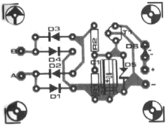
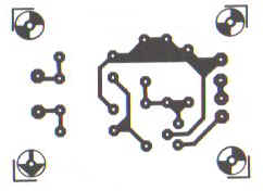
PCB


Parts List
|
Title: Phone line indicator
electronic circuit
Source: smartkit
Published on: 2005-02-10
Reads: 552
Print version: ![]()
Other electronic circuits and schematics from Telephone related
-
Phone Broadcaster
-
Telephone Audio Interface
-
Phone Busy Indicator
-
Telephone line monitor
-
Telephone amplifier
-
Off line Telephone tester
-
Telephone Hold Button
-
Detector of cellular phone incoming call
-
Telephone line based audio muting and light on circuit
-
Telephone Headgear
