Off line Telephone tester
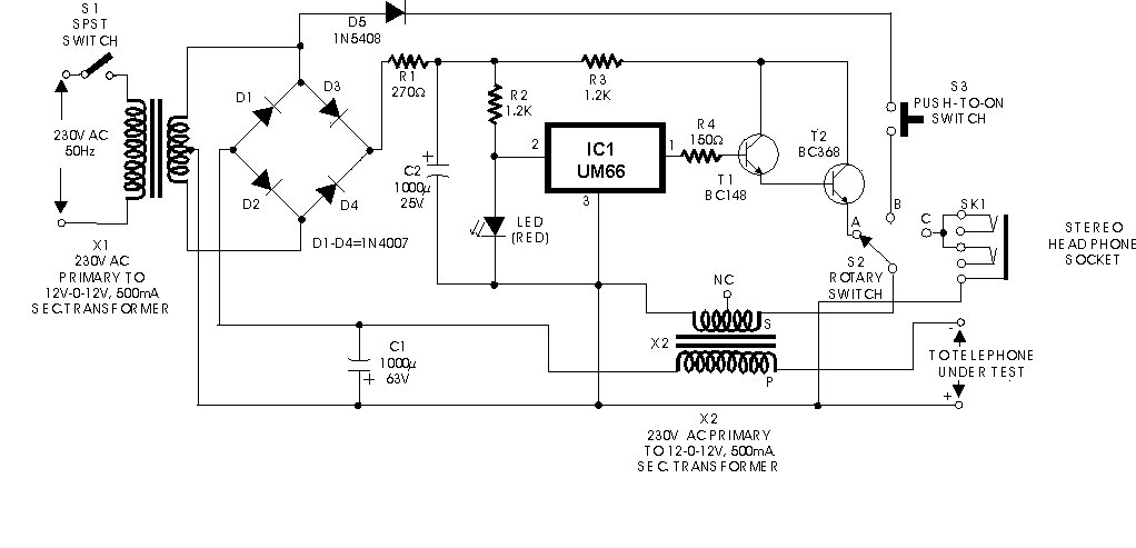
H ere is a circuit of an off-line telephone tester which does not require any
telephone line for testing a telephone instrument. The circuit is so simple that
it can be easily assembled even by a novice having very little knowledge of
electronics. A telephone line may be considered to be a source of some 50 volts
DC with a source impedance of about 1 kilo-ohm. During ringing, in place of DC,
an AC voltage of 70 to 80 volts (at 17 to 25 Hz) is present across the telephone
line. When the subscriber lifts the handset, the same is sensed by the telephone
exchange and the ringing AC voltage is disconnected and DC is reconnected to the
line. Lifting of the handset from the telephone cradle results in shunting of
the line’s two wires by low impedance of the telephone instrument. As a result,
50V DC level drops to about 12 volts across the telephone instrument. During
conversation, the audio gets superimposed on this DC voltage. Since any DC
supply can be used for testing a telephone instrument, the same is derived here
from AC mains using step-down transformer X1. Middle point of the transformer’s
secondary has been used as common for the two full-wave rectifiers—one
comprising diodes D1 and D2 together with smoothing capacitor C1 and the other
formed by diodes D3 and D4 along with filter capacitor C2. The former supplies
about 12 volts for the telephone instrument through primary of transformer X2
which thus simulates a source impedance, and a choke which blocks AC audio
signals present in the secondary of transformer X2. The AF signal available in
secondary of X2 is sufficiently strong to directly drive a 32-ohm headset which
is connected to the circuit through headphone socket SK1 via rotary switch S2.
During ringing, a pulsating DC voltage from transformer X1 via rectifier diode
D5, push-to-on switch S3, and contact ‘B’ of rotary switch S2 is applied across
secondary of transformer X2. The boosted voltage available across primary of
transformer X2 is sufficient to drive the ringer in the telephone instrument.
Please avoid pressing of switch S3 for more than a few seconds at a time to
prevent damage to the circuit due to high voltage across primary of transformer
X2. The circuit also incorporates a music IC (UM66) whose output is connected to
secondary of transformer X2 via switch S2 after suitably boosting its output
with the help of darlington transistor pair T1 and T2. This output can be used
to test the audio section of any telephone instrument. After having assembled
the circuit satisfactorily, the following procedure may be followed for testing
a telephone instrument:
1. Connect the telephone to the terminals marked ‘To Telephone Under Test’and
switch on mains (switch S1).
2. To test the ringer portion, flip switch S2 to position ‘B’ and press S3 for a
moment. You should hear the ring in case the ringer circuit of the telephone
under test is working. Please ensure that handset is on cradle during this test.
3. For testing the audio section, flip switch S1 to position ‘C’ and connect a
headphone to socket SK1. Pick the telephone handset and speak into its
microphone. If audio section is working satisfactorily, you should be able to
hear your speach via the headphone. If you dial a number, you should be able to
hear the pulse clicks or pulse tone in the headphone, depending on whether the
telephone under test is functioning in pulse or tone mode. If the telephone
under test has a built-in musical hold facility, on pressing the ‘hold’ button
you should be able to hear the music. Now flip switch S2 to position ‘A’. You
should be able to hear music generated by IC1 through earpiece of the handset of
the telephone under test, indicating propor functioning of the AF amplifier
section. The circuit can be assembled on a small piece of veroboard. Try to
mount the two transformers on opposite sides of the board, displaced by 90
degrees. Always keep handy multi-type modular plugs for testing various types of
telephones. Mount all switches, sockets and LEDs on the front of testing panel.
Title: Off line Telephone tester
electronic circuit
Source: www.electronic-circuits-diagrams.com
Published on: 2005-02-09
Reads: 590
Print version: ![]()
Other electronic circuits and schematics from Telephone related
-
Telephone Hold Button
-
Telephone Audio Interface
-
Telephone Ringer using 556 dual timers
-
The Link Telephone Intercom – Every Home Should Have One!
-
Phone line indicator
-
Telephone line monitor
-
Two line intercom plus a telephone changeover switch
-
Phone "Hold" With Music
-
Telephone Headgear
-
Telephone amplifier