SmartCard PC Emulator
WARNING: In order to build the adapter described below, you will at least require some basic hobby electronics experience. If you don't understand, how the described circuitry works, better don't use it! Although the described procedure is relatively secure, serious errors might in the worst case damage both your PC and your smartcard system.
Introduction
This smartcard adapter follow exactly the specification
ISO 7816.
Also, the protocol is the "asynchronous half duplex T=0 protocol" with "active
low reset" and "inverse convention" as defined in this standard.
The following description may be used in order to connect computers to
ISO 7816
compatible chip card systems (e.g. GSM mobile phones or other pay-TV decoding
systems) if they also use asynchronous transmission. For smart card systems
which use synchronous transmission (e.g. most phone cards) the interface
described here will need some modifications.
According to ISO, a chip card is 85.60 mm long, 53.98 mm high, 0.76 mm thick and
the edges are rounded with a radius of 3.18 mm. It has eight defined contact
areas (C1 - C8 in the diagram below), each of which is at least 2 mm wide and
1.7 mm heigh.
You can produce your card adapter by making a PCB with contact areas at the
above listed locations.
The PCB must have precisely the thickness and width of a real card, but it may
be longer, so that you can locate the interface electronics on the part which
remains outside the slot.
Normal PCBs are about 1.3 mm think and won't fit into the slot.
Either you get a PCB which is about 0.8 mm thick or you make it thinner, e.g. by
using a sander machine.
The adapter will only need the card contacts I/O, GND, RST and VCC.
On the RS-232 side, the following contacts will be used:
| Symbol | Sub-D 25-pin | Sub-D 9-pin | Description |
|---|---|---|---|
| TXD | 2 | 3 | Transmit Data |
| RXD | 3 | 2 | Receive Data |
| RTS | 4 | 7 | Request To Send |
| CTS | 5 | 8 | Clear To Send |
| DSR | 6 | 6 | Data Set Ready |
| GND | 7 | 5 | Ground |
| DCD | 8 | 1 | Carrier Detect (here: reset) |
| DTR | 20 | 4 | Data Terminal Ready |
The pins DTR, DSR and CTS are not actually needed, they are just connected together in the adapter, so that defined levels are available on them because some software might need this.
Electric Scheme
(also connected to 74LS07: pin 7=GND, pin 14=VCC)
Components List
| Item | Component | Description |
|---|---|---|
| 1 | BASE | 0.5-0.8 mm PCB single sided |
| 1 | U1 | IC Maxim MAX232CPE (or Linear Technology LT1081CN) |
| 1 | U2 | IC 74LS07 (or 7407) |
| 5 | C1,C2,C3,C4,C5 | capacitors 1 uF (or higher), 16 V |
| 2 | R1,R2 | resistors 220 Ohm |
| 1 | D1 | diode LED standard RED |
| 1 | D2 | diode LED standard GREEN |
| 1 | CON1 | female Sub-D connector (9 or 25-pin) |
| 1 | CAB | 4 pin + shield low voltage computer cable |
PCB Layout
Click
Here to download big pictures (smcpcb.zip).
Note: if you want to print real size images remember these settings:
Note that all images are 1:1 at 1200 x 1200 DPI
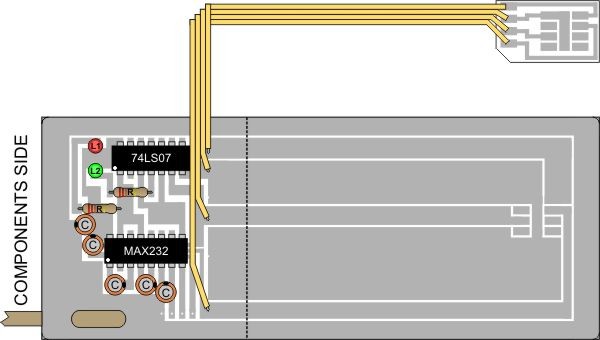
Optional Small SmartCard Adapter (normally used on GSM phones)
Components side
IC's Pinouts
 |
 |
 |
 |
Circuit Description
The MAX232 converts the RS-232 levels (about +10 and -10 V) to TTL voltage (0
and +5 V) and vice versa without requiring anything else than +5 V power supply.
This chip contains two TTL->RS-232 and two RS-232->TTL drivers and needs four
external 1 uF capacitors in order to generate the RS-232 voltage internally. The
adapter electronic gets its power supply from the smartcard reader device VCC
line or you can use an external 5 V supply if you wish.
The card slot's RST line is connected using one of the TTL->RS-232 drivers in
the MAX232 to DCD, so that the software and the reader can easily resynchronize
in case of a protocol error.
The I/O line is a bidirectional half-duplex asynchronous TTL level serial port.
We can connect this line to a MAX232 TTL input driver (which is connected to RxD
and sends bytes to the PC) in order to receive data from the reader. The TxD
signal is converted in the MAX232 to TTL level and is connected with an open
collector TTL driver to I/O. This open collector driver (one of six in the
74LS07) has a high impedance output during idle state and 1 and is connected to
GND during a 0 on it's input. As there is already a pull-up resistor to +5 V on
I/O in the smartcard reader device, this circuitry guarantees, that the adapter
is in high impedance state if the TxD line is idle and delivers the correct
voltage if the PC sends bytes and the smartcard reader device is in reception
mode. As we don't connect totem-pole or tristate outputs to I/O, a short circuit
should be impossible in the adapter.
Pay attention to the polarity of the capacitors (marked with a + in the diagram
next to each capacitor)! The -->-- symbols in the MAX232 diagram above indicate
the voltage converters inside the chip. The RED LED show you when the reader
activates the interface. The GREEN LED show you the I/O traffic. The capacitor
between VCC and GND is not absolutely necessary but recommended.
As a side effect of this simple interface design, every byte sent by the PC is
at the same time also received by the PC. Consequently, you can test the circuit
with a terminal emulator and external +5 V supply by switching of local echo: if
you still see every typed character immediately on the screen, the interface
should be all right. Software must be capable of dealing with this echo from the
interface. As specified in the ISO standard, the reader activates VCC only
shortly before a reset and deactivates VCC again if an answer-to-reset packet
isn't received from the card in time after the reset signal.
A few additional hints
If you have a larger distance between the PC an the smartcard reader device,
then locate the adapter electronic near the reader, because the RS-232 interface
is much more suitable for long cables than the TTL signals. Cables of 12 m
length have sucessfully been used and you shouldn't have problems with RS-232
cables up to 25 m length and more.
You can also use this adapter circuit to allow a PC to listen to the data
traffic between a reader and a real card. Just connect the real card and the
adapter parallel to the reader and don't let the PC software transmit anything.
For more details about the protocol, check
ISO 7816-3
standard.
There are many alternative ways to build this interface if you don't have some
of the components available. E.g. the MAX232 could be replaced by the fully
compatible LT1081 from Linear Technology. The circuit still works fine if you
use higher capacitors than 1 uF (e.g. my prototype worked fine with 4 22 uF
types which were left from a previous project), but use equally sized capacitors.
If you use the pin compatible MAX220 (a low power version) instead of the
MAX232, then use capacitors with 10 uF or higher. The MAX232 should be the
easiest available one of these chips.
If you don't have the experience to etch your own PCB (it's not very difficult)
or don't know someone who does, then you could solder the components in a
universal raster PCB or plug them into an experimental board. Then produce just
a simple PCB with only the ISO card contacts and connections to outside the
smartcard reader device by mechanically removing the thin copper layer with a
good knive between the 4 contacts and lines.
Peoples have also suggested to use an empty German phone card, which also has
ISO contacts. Remove the integrated chip from the other non-contact side, test
whether the contacts are now isolated from each other and use a special
conductive ink you'll find in an electronics store in order to draw connections
to the end of the card were you connect wires. I haven't tested this and don't
know how well it works, but you might also consider it.
A few final remarks about the security of the adapter
Normally, both the RS-232 interface and the smartcard reader device slot should not be harmed by short circuits, but be careful. Also try to avoid electrostatic voltage (e.g. generated by walking on a suitable carpet) near the interface, because discharges cause easily reader or PC crashes and could theoretically even harm the hardware (especially CMOS chips like the 74HC04). Before connecting the reader and the PC the first time, you might want to check the voltage between the two GND lines. In correct installations, the difference of the GND potentials is very low (below 1 V), but someone has reported up to 50 V (high impedance only). Most smartcard reader devices are not connected with the earth line, so their GND potential is floating or sometimes only defined by e.g. the shielding of the antenna cable. If your antenna system is not correctly installed, the shield might also not be grounded. One quick solution might be to switch off all components and then connect first the RS-232 GND line to the GND of your smartcard reader device before connecting anything else. You might also design the ISO contacts on the PCB so that GND touches all pins at first when the PCB is inserted in the card slot. The only really secure protection between your PC and your smartcard reader device would be to use an isolating RS-232 driver (e.g. you might want to check data sheets of Maxim's MAX250/251/252 chips which offer RS-232 protection up to 1500 V), but under normal circumstances you won't need this.
Software
We do not offer any software support. Try to search using search engines or
build your own software.
Title: SmartCard PC Emulator
electronic circuit
Source: www.electronics-lab.com
Published on: 2005-02-10
Reads: 1530
Print version: ![]()
Other electronic circuits and schematics from Miscellaneous
-
Whistle Responder
-
Time Delay Relay
-
Time Delay Relay II
-
Digital Step-Km Counter
-
Simple Lie Detector
-
Cellular Phone calling Detector
-
7 Segment LED Counter
-
S-video to RCA
-
Nocturnal Animals Whisker
-
Economy radar detector