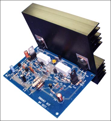
100W Audio Amplifier
|
 |
How it Works
The circuit works from a symmetrical ρ40 VDC power supply and draws a maximum
current of 2.6 A. The input circuit of the amplifier is a differential amplifier
built around Q4 and Q5 that employ DC feedback thus preventing any DC voltage
from appearing across the speaker with the usual destructive results. Q11 acts
as a current source and ensures that the input stage draws a constant current of
1 mA. The signal which appears as a voltage drop across the resistor connected
in series with the collector of Q4 is used to drive the DARLINGTON pair Q3, Q2
which together with the constant current source of 7 mA that is Q10, form the
driver stage. This stage operates in class A and is driving the complementary
output stage Q1, Q9. The transistor Q7 is used to balance the circuit at
different temperatures and must be mounted on the heatsink between the out put
transistors. The feedback loop which consists of R8, R9, C2, C3 provides AC
stability to the circuit. The circuit also incorporates a protection stage that
makes it virtually indestructible. This protection circuit is built around Q6,
Q8. If for whatever reason the output remains connected on one supply rail and
the common the output is also protected from high DC voltages that could burn
the speakers. The supply rails should be protected by 2 A fuses for the 8 ohm
version and 3 A for the 4 ohm.
Technical Specifications - Characteristics
Output power (f=1 KHz, d=0.5 %): 100 W in 8 ohm
Supply voltage: ................ ρ 40 V
Quiescent current: ............. 50 mA
Maximum current: ............... 2.6 A
Sensitivity: . 600 mV
Frequency response: ............ 10-35000 Hz (-1 dB)
Distortion HD: ................. 0.01 %
Intermodulation dist.: ......... 0.02 %
Signal/noise: 83 dBConstruction
------------------------------------------------------------------------------------
Download +/- 40V Power Supply schematics
------------------------------------------------------------------------------------
PLEASE READ THIS BEFORE YOU START CONSTRUCTION
To cater for those who wish to use 4 ohm speakers with this amplifier the Kit
includes the necessary components for both versions. The components that differ
are R3,4,17 and 23. If you build the 8 ohm version then you must also include in
the circuit R28 and D7, D8 which are not used in the 4 ohm version. As you see
all the components are already marked on the component side of the p.c. board.
The construction is made this way much simpler. Start the construction from the
pins and the jumper connections, continue with the resistors and the capacitors
and last solder in place the semiconductors. Check each resistor before
soldering it, to see if
its colours match those in the component list. Be careful with the electrolytic
capacitors because their polarity should be respected. The polarity of those
capacitors is marked on their bodies and on the component side of the p.c. board.
NOTE: On the p.c. board next to R2, R16 are marked two other resistors which do
not appear in the circuit diagram but are included in the components. They are
of 1 ohm 2 W (brown, black, gold) and must be included in the circuit. Take care
when you are soldering the semiconductors because if you overheat them they can
be damaged. The output transistors should be mounted on the heatsink that is
included in the kit. Take care not to short circuit them with the heatsink and
we
recommend that you use some HTC between the transistor body and the sink in
order to improve heat dissipation. Follow the diagram for the mounting of the
power transistors as it shows clearly how to insert the insulators and the
screws. Q7 should be made to touch the heatsink and is a good idea to use a bit
of HTC between its casing and the surface of the heatsink. When you finish the
construction of your project clean the board thoroughly with a solvent to remove
all flux residues and make a careful visual inspection to make sure there are no
mistakes, components missing and short circuits across adjacent tracks on the
board. If everything is OK you can make the following connections: Input: 3 (signal),
5 (common) Output: 7 (signal), 6 (common) Supply: 1 (-40 VDC), 2 (+40 VDC) 5 (0
VDC)
Connect a milliammeter in series with the power supply, short the input of the
amplifier, turn the power ON and adjust the trimmer P1 so that the quiescent
current is about 50 mA. When you finish this adjustment remove the shunt from
the input and connect the output of a preamplifier to it. Connect the pre
amplifier to a suitable source and turn everything ON. The signal should be
heard from the speakers clear and undistorted. First of all let us consider a
few basics in building electronic circuits on a printed circuit board. The board
is made of a thin insulating
material clad with a thin layer of conductive copper that is shaped in such a
way as to form the necessary conductors between the various components of the
circuit. The use of a properly designed printed circuit board is very desirable
as it speeds construction up considerably and reduces the possibility of making
errors. Smart Kit boards also come pre-drilled and with the outline of the
components and their identification printed on the component side to make
construction easier. To protect the board during storage from oxidation and
assure it gets to you in perfect condition the copper is tinned during
manufacturing and covered with a special varnish that protects it from getting
oxidised and makes soldering easier. Soldering the components to the board is
the only way to build your circuit and from the way you do it depends greatly
your success or failure. This work is not very difficult and if you stick to a
few rules you should have no problems. The soldering iron that you use must be
light and its power should not exceed the 25 Watts. The tip should be fine and
must be kept clean at all times. For this purpose come very handy specially made
sponges that are kept wet and from time to time you can wipe the hot tip on them
to remove all the residues that tend to accumulate on it. DO NOT file or
sandpaper a dirty or worn out tip. If the tip cannot be cleaned, replace it.
There are many different types of solder in the market and you should choose a
good quality one that contains the necessary flux in its core, to assure a
perfect joint every time.
DO NOT use soldering flux apart from that which is already included in your
solder. Too much flux can cause many problems and is one of the main causes of
circuit malfunction. If nevertheless you have to use extra flux, as it is the
case when you have to tin copper wires, clean it very thoroughly after you
finish your work. In order to solder a component correctly you should do the
following:
- Clean the component leads with a small piece of emery paper. - Bend them at the correct distance from the component body and insert the component in its place on the board.
- You may find sometimes a component with heavier gauge leads than usual, that
are too thick to enter in the holes of the p.c. board. In this case use a mini
drill to enlarge the holes slightly. Do not make the holes too large as this is
going to make soldering difficult afterwards.
- Take the hot iron and place its tip on the component lead while holding the
end of the solder wire at the point where the lead emerges from the board. The
iron tip must touch the lead slightly above the p.c. board.
- When the solder starts to melt and flow, wait till it covers evenly the area around the hole and the flux boils and gets out from underneath the solder. The whole operation should not take more than 5 seconds. Remove the iron and leave the solder to cool naturally without blowing on it or moving the component. If everything was done properly the surface of the joint must have a bright metallic finish and its edges should be smoothly ended on the component lead and the board track. If the solder looks dull, cracked, or has the shape of a blob then you have made a dry joint and you should remove the solder (with a pump, or a solder wick) and redo it.
- Take care not to overheat the tracks as it is very easy to lift them from
the board and break them.
- When you are soldering a sensitive component it is good practice to hold the
lead from the component side of the board with a pair of long-nose pliers to
divert any heat that could possibly damage the component.
- Make sure that you do not use more solder than it is necessary as you are running the risk of short-circuiting adjacent tracks on the board, especially if they are very close together.
- When you finish your work cut off the excess of the component leads and clean
the board thoroughly with a suitable solvent to remove all flux residues that
still remain on it.

If it does not work
Check your work for possible dry joints, bridges across adjacent tracks or
soldering flux residues that usually cause problems. Check again all the
external connections to and from the circuit to see if there is a mistake there.
- See that there are no components missing or inserted in the wrong places.
- Make sure that all the polarised components have been soldered the right way
round. - Make sure the supply has the correct voltage and is connected the right
way round to your circuit.
- Check your project for faulty or damaged components. If everything checks and your project still fails to work, please contact your retailer and the Smart Kit Service will repair it for you.

or


L1 : 10 turns with wire 0,5mm turned on a restistor of 1W
If you use a 4Ohm speaker you will place R3,4,17,23 at the board.
If you use a 8Ohm speaker you will place D7 D8 and R28.
For R2 and R16 if you don't find a 0,47Ohm place two of 1 Ohm parallel.
R16 must be 0,47Ohm...the 1Ohm must be a typographical error, take care of this, i haven't tested it.
Title: 100W Audio Amplifier
electronic circuit
Source: smartkit
Published on: 2005-02-01
Reads: 6976
Print version: ![]()
Other electronic circuits and schematics from Audio
-
Digital Volume Control
-
Sound Controlled Filp Flop
-
1.5W Audio power amplifier (12V)
-
Three-Level Audio Power Indicator
-
Stereo Channel Selector
-
16w Bridge Amplifier
-
100W Guitar Amplifier
-
5 band graphic equalizer using a single IC/chip
-
Add on Stereo Channel Selector
-
Band 2 Preamplifier