Which way round?
If you’ve connected the circuit up correctly, the LED should now be on. This proves that current is flowing. To calculate exactly what current we can use Ohm’s law. Let’s assume that the total battery voltage of 9 V is dropped across the resistor and that no voltage occurs across the two diodes. In fact, there is voltage across the diodes, but we needn’t worry about it yet, as it is only a small amount. We’ll measure it, however, soon.
Now, with a resistance of 1k5, and a voltage of 9 V, we can calculate the current flowing, as:
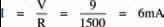
The next thing to do is to turn around the diode, so that its cathode is more positive, as in the circuit of Figure 6.5. The breadboard layout is the same with anode and cathode reversed, so we needn’t redraw it.
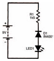
Figure 6.5 The circuit again, but with the diode reversed
What happens? You should find that absolutely nothing happens. The LED does not light up, so no current must be flowing. The action of reversing the diode has resulted in the stopping of current. We can summarise this quite simply in Figure 6.6.
Figure 6.6(a) shows a diode whose anode is positive with respect to its cathode. Although we’ve shown the anode as positive with a + symbol, and the cathode as negative with a – symbol, they don’t necessarily have to be positive and negative. The cathode could for example be at a voltage of +1000 V if the anode was at a greater positive voltage of, say +1001 V. All that needs to occur is that the anode is positive with respect to the cathode.
Under such a condition, the diode is said to be forward biased and current will flow, from anode to cathode.
When a diode is reverse biased i.e., its cathode is positive with respect to the anode, no current flows, as shown in Figure 6.6(b). Obviously, something happens within the diode which we can’t see, depending on the polarity of the applied voltage to define whether current can flow or not. Just exactly what this something is, isn’t necessary to understand here. We needn’t know any more about it here because we’re only concerned with the practical aspects at the moment; and all we need to remember is that a forward biased diode conducts, allowing current to flow, while a reverse biased diode doesn’t.
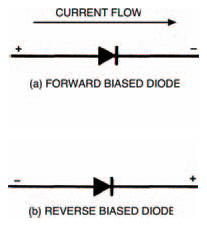
Figure 6.6 Circuit diagrams for forward and reverse biased diodes
What we do need to consider in more detail; however, is the value of the current flowing, and the small, but nevertheless apparent, voltage which occurs across the diode, when a diode is forward biased (the voltage we said earlier we needn’t then worry about). The following experiment will show how the current and the voltage are related.
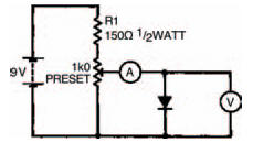
Figure 6.7 A circuit to test the operation of a forward biased diode
Table 6.1 This is half complete, add the results of your experiment
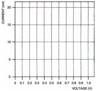
Figure 6.8 A blank graph for you to plot the results of your experiment
Figure 6.7 shows the circuit you have to build. You’ll see that two basic measurements need to be taken with your meter. The first measurement is the voltage across the forward biased diode, the second measurement is the current through it. Each measurement needs to be taken a number of times as the preset is varied in an organised way. Table 6.1, which is half complete, is for you to record your results, and Figure 6.8 is a blank graph for you to plot the results into a curve. Do the experiment the following way:
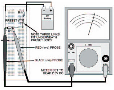
Figure 6.9 The breadboard layout for the circuit in Figure 6.7
- set up the components on the breadboard to measure only the voltage across the diode. The breadboard layout is given in Figure 6.9. Before you connect your battery to the circuit, make sure the wiper of the preset is turned fully anticlockwise,
- adjust the preset wiper clockwise, until the first voltage in Table 6.1 is reached,
- now set up the breadboard layout of Figure 6.10, to measure the current through the diode — the breadboard layout is designed so that all you have to do is take out a short length of single-strand connecting wire and change the position of the meter and its range. Record the value of the current at the voltage of step 2,
- change the position of the meter and its range, and replace the link in the breadboard so that voltage across the diode is measured again,
- repeat steps 2, 3 and 4 with the next voltage in the table,
- repeat step 5 until the table shows a given current reading. Now set the current through the diode to this given value and measure and record the voltage,
- set the current to each value given in the table and record the corresponding voltage, until the table is complete.
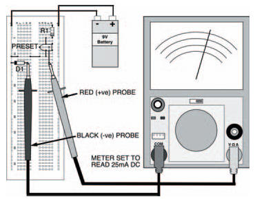
Figure 6.10 The same circuit, set up to measure the current through the diode
<< Diodes I