Voltages
When you measure voltages with your multi-meter the same procedure should be followed, using the highest voltage ranges first and stepping down as required. The voltages you are measuring here are all direct voltages as they are taken from a 9 V d.c. battery. So you needn’t bother using the three highest d.c. voltage ranges on the multi-meter, as your 9 V battery can’t generate a high enough voltage to damage the meter anyway. Also, don’t bother using the a.c. voltage ranges as they’re — pretty obviously — for measuring only alternating (that is, a.c.) voltages.
As an example you can build the circuit of Figure 3.9 up on your breadboard, shown in Figure 3.11. What is the measured voltage? It should be about 4.5 V.
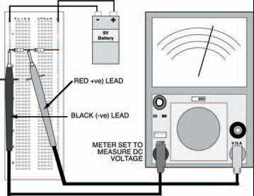
Figure 3.11 A breadboard layout for the circuit in Figure 3.9: measuring the voltage across R2. This will be the same as R1, and each will be around 4.5 V — half the battery voltage
Now measure the voltage across the other resistor — it’s also about 4.5 V. Well, that figures, doesn’t it? There’s about 4.5 V across each resistor, so there is a total of 2 x 4.5 V that is, 9 V across them both: the voltage of the battery. This has demonstrated that resistors in series act as a voltage divider or a potential divider, dividing up the total voltage applied across them. It’s understandable that the voltage across each resistor is the same and half the total voltage, because the two resistors are equal. But what happens if the two resistors aren’t equal?
Build up the circuit of Figure 3.12. What is the measured voltage across resistor R2 now? You should find it’s about 2.1 V. The relationship between this result, the values of the two resistors and the applied battery voltage is given by the voltage divider rule:

where Vin is the battery voltage and Vout is the voltage measured across resistor R2.
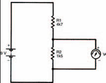
Figure 3.12 A circuit with two unequal, series resistors. This is used in the text to illustrate the voltage divider rule, one of the most fundamental rules of electronics
We can check this by inserting the values used in the circuit of Figure 3.12:
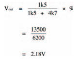
In other words, close enough to our measured 2.1 V to make no difference. The voltage divider rule, like Ohm’s law and the laws of series and parallel resistors, is one of the fundamental laws which we must know. So, remember it! ok?
Take note
By changing resistance values in a voltage divider, the voltage we obtain at the output is correspondingly changed. You can think of a voltage divider almost as a circuit itself, which allows an input voltage to be converted to a lower output voltage, simply by changing resistance values.
Pot-heads
Certain types of components exist, ready-built for this voltage dividing job, known as potentiometers (commonly shortened to just pots). They consist of some form of resistance track, across which a voltage is applied, and a wiper which can be moved along the track forming a variable voltage divider. The total resistance value of the potentiometer track doesn’t change, only the ratio of the two resistances formed either side of the wiper. The basic symbol of a potentiometer is shown in Figure 3.13(a).
A potentiometer may be used as a variable resistor by connecting the wiper to one of the track ends, as shown in Figure 3.13(b). Varying the position of the wiper varies the effective resistance from zero to the maximum track resistance. This is useful if we wish to, say, control the current in a particular part of the circuit; increasing the resistance decreases the current and vice versa.
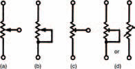
Figure 3.13 A variety of symbols used for variable resistors, or potentiometers
These two types of potentiometer are typically used when some function of an appliance e.g., the volume control of a television, must be easily adjustable. Other types of potentiometer are available which are set at the factory upon manufacture and not generally touched afterwards e.g., a TV’s height adjustment. Such potentiometers are called preset potentiometers. The only difference as far as a circuit diagram is concerned is that their symbols are slightly changed. Figures 3.13(c) and (d) show preset potentiometers in the same configurations as the potentiometers of Figures 3.13(a) and (b). Mechanically, however, they are much different.
Meters made
The actual internal resistance of a multi-meter must be borne in mind when measuring voltages as it can affect measurements taken. We can build a circuit (Figure 3.14) which shows exactly what the effect of multi-meter resistance is. As both resistors in the circuit are equal, we can see that the measured voltage should be half the battery voltage that is, 4.5 V (use the voltage divider rule, if you don’t believe it!). But when you apply your multi-meter across resistor R2 you find that the voltage indicated is only about 3 V.
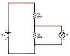
Figure 3.14 A circuit which is used to show the effect of the meter’s own resistance in a circuit
The fact is that when the multi-meter is not connected to the circuit the voltage is 4.5 V, but as soon as the multi-meter is applied, the voltage across resistor R2 falls to 3 V. Also, the voltage across resistor R1 rises to 6 V (both voltages must add up to the battery voltage, remember). Applying the multi-meter affects the operation of the circuit, because the multi-meter resistance is in parallel with resistor R2.
<< Practically there