Ohms per volt
A meter’s internal resistance is stated as a number of ohms per volt. For example, the resistance of the meter we use in this book is 20,000 ohms per volt (written 20 kΩV-1) on d.c. voltage scales so when it’s to read 4.5 V, it’s resistance is 90 k. This resistance, in parallel with resistor R2 forms an equivalent resistance, given by the law of parallel resistors, of:
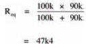
This resistance is now the new value of R2 in the circuit so, applying the voltage divider rule, the measured voltage will be:
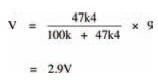
which is roughly what you measured (hopefully).
Any difference between the actual measurement and this calculated value may be accounted for because this lower voltage causes a lower multi-meter resistance which, in turn, affects the voltage which, in turn, affects the resistance, and so on until a balance is reached. All of this occurs instantly, as soon as the multi-meter is connected to the circuit.
What this tells us is that you must be careful when using your multi-meter to measure voltage. If the circuitunder- test’s resistance is high, the multi-meter resistance will affect the circuit operation, causing an incorrect reading.
Any multi-meter will affect operation of any circuit to a greater or lesser extent — but the higher the multimeter resistance compared with the circuit resistance, the more accurate the reading.
Hint:
A good rule-of-thumb to ensure reasonably accurate results is to make sure that the multi-meter resistance is at least ten times the circuit’s resistance.
Fortunately, because of their very nature, digital multi-meters usually have an internal resistance in the order of millions of ohms; a fact which allows it to accurately measure voltages in circuits with even high resistances.
Well. We’ve reached the end of this chapter, so how about giving the quiz over the page a go to see if you’ve really learned what you’ve been reading about.
<< Voltages