Balanced Low Noise Microphone Preamp
Introduction
This simple design has very low noise, close to the theoretical minimum, high hum rejection and variable gain with a single rotary pot. It is similar to that used in many professional grade mixing desks and can form the basis of a no compromise recording mixer for live work.
The design consists of differential compound pairs of transistors with a common mode (floating) gain control connecting the emitters of the pair. The compound pairs of 2N4403 and BC549s are far more linear than any single transistor. The circuit is differential in and out and therefore requires a balanced to unbalanced buffer to give suitable output for the next signal stages of a channel in a mixing desk. This is provided by a high performance op-amp differential gain stage, which can be a TL071 or similar IC of your choice. The stage has a gain of six or 15 dB and that sets the maximum input level at about 1.5 volts rms before clipping. This equals an SPL of over 150dB with a typical microphone!
Full gain is 1000 times or 60dB. Distortion is low to unmeasurable because it is below the noise level at high gains. The CMRR (Common Mode Rejection Ratio) is well over 60 dB and better than any available mic cable as far as hum rejection is concerned. The bandwidth extends beyond 100kHz, and no RF suppression is shown as it has proved unnecessary in practice. The input impedance or load on the mic is set by the two 3.3k ohm resistors. This will suit almost any mic with a nominal impedance of 150 to 600 ohms.
Description
The input stage is configured for least noise and this has meant a non IC approach. There are some special ICs that can be used for mic pre-amps, they contain a circuit like this one except fabricated on one chip. Examples include the SSM2017 (now obsolete) or the replacement INA103 or similar.
Components should all be readily available except for the 10 k ohm pot for the gain control. This needs to be a reverse log taper - or else use a multi-position switch with 6 dB gain steps covering the 60 dB range of the circuit. Make sure it is make before break.
Editor's Note - Alternatively, a standard log pot can be used, but wired "backwards". This will work fine if it is labelled "Attenuation" instead of "Gain". As the pot is advanced clockwise, the gain is reduced (attenuation is increased). Maximum gain will therefore be applied when the pot is fully anti-clockwise. Note that this is not a problem that is specific to this circuit - all the IC mic preamps have exactly the same problem.
The +/-15 Volt power supply is important too, it must be regulated and low noise. If the usual voltage regulator ICs are used I recommend fitting a post filter consisting of a 10 ohm resistor and a 470 uF capacitor to remove any noise generated in the ICs (as shown in Figure 1). Some 7815 ICs could be sold as noise generators, the adjustable voltage ones (LM317, LM337) are very much quieter. A single regulator board may be used to power multiple preamps, with each preamp having its own post filter circuits. Because of the extensive filtering applied, the P05 (Rev-A) power supply is recommended for this preamp.
Figure 1 - Complete Microphone Preamp
Good quality components should be used with metal film resistors in the collectors and emitters of the input pairs for least noise. Where a resistor has significant DC voltage imposed on it in high gain circuits always use low noise types. Metal film resistors are about the best only bettered by wire wound which is a bit impractical. Avoid cermet, metal glaze, and very old carbon composition types. Also avoid bead tantalum capacitors, as they go leaky and crackle. They are just about the most fragile electronic components made. The 100nF capacitor (C6) should be mounted as close as possible to the opamp supply pins - a ceramic cap is recommended for best bypass performance at high frequencies.
The 1000uF capacitor can be a normal electrolytic of 10 or 16 volts rating. There is usually no problem with zero DC bias on modern electros. All other electros should be 25V rating as a minimum.
Upon checking the published specs for the SSM2017 in regards to noise, my workshop version of the preamp measures at least as good with a 200 ohm source resistance (typical of most dynamic microphones).
EIN = 0.27 uV rms in 20 kHz bandwidth with 200 ohm source.
= 1.9 nV per root Hz (equal to spec for SSM2017)
Noise Figure = 0.9 dB rel 200 ohms.
Editor's Comment
I would suggest that 1% metal film resistors should be used throughout this circuit - the additional cost is negligible, and this will also ensure that the balanced buffer stage (U1) is properly balanced. Even a small error in the input and feedback components will degrade the common mode rejection.
Like Phil, I also recommend against the use of tantalum capacitors, and regular readers will notice that I have not suggested them for any project (although there was one suggestion that you could use them if you wanted to). The only capacitor fault I have ever had to track down with an intermittent short circuit was a tantalum bead type - it was neither fun, nor easy to find :-(
As with all circuits presented on these pages, feel free to experiment. The 2N4403 transistors may prove difficult for some readers to obtain, and BC559s can be substituted with some possible increase in noise. I would expect that any increase will be acceptable for most applications. Performance should otherwise be much the same as described.
The preamp is ideal for portable use, and can be operated from a pair of 9V batteries.
Note: The Revision-A PCB is now available for this preamp. There are a couple of very minor changes to the circuit, and the board is a dual preamplifier - two completely independent microphone preamps on one PCB. Included with the construction data (available when you purchase the PCB) is a circuit for a switched gain control, which provides much more linear control than you will get from a pot. The new PCB is double sided, and includes a full-sized ground-plane to help minimise noise.
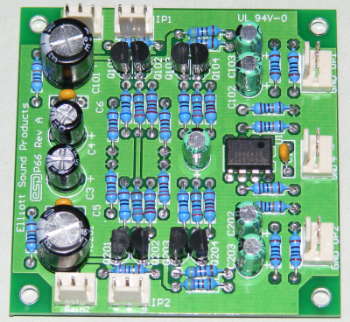
Figure 2 - Photo of the Completed Revision-A PCB
In all, this preamp is highly recommended for professional or semi-professional use, wildlife recording or just experimenting. As you can see from the photo, the board is very compact, and I have described a phantom feed supply and distribution board elsewhere in the project section, along with a phantom powered microphone amplifier and a series of microphone projects.
Footnote
When looking at IC specifications, you often see noise specified as nV√Hz. This doesn't mean a lot to most DIY people, but it's actually easy to calculate the equivalent input noise from this. If we assume the bandwidth to be from 20-20kHz, that's a range of 19980 Hz.
Now, take the square root of this value and multiply by the noise figure quoted. For most normal audio work, a value of 141 is fine for the square root. Therefore ...
Equivalent input noise (EIN) = 141 * Noise (nV)
Output noise = EIN * Gain
If the stage gain is 100 and EIN is 1uV, output noise is 100uV. It is now easy so see if this will cause a problem with your signal. For example, if the signal you are trying to amplify is only 1mV, you will only have a 20dB signal to noise ratio (SNR). If your input signal is 50mV, SNR is now 54dB (not wonderful, but may be ok for your application).
Title: Balanced Low Noise Microphone Preamp
electronic circuit
Source: unknown
Published on: 2012-09-20
Reads: 2768
Print version: ![]()
Other electronic circuits and schematics from Audio
-
Headphone Monitoring Switch
-
22 Watt Audio Amplifier
-
Automatic Loudness Control
-
Three-Level Audio Power Indicator
-
3 Line Mixer
-
Two transistor audio amplifier circuit
-
3 Channel Spectrum Analyzer
-
Precision Audio Millivoltmeter
-
Audio Visual Indicator for Telephones
-
Audio Distribution Amplifier