Parallel Port Relay Interface
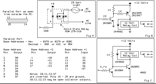
Below are three examples of controlling a relay from the PC's parallel printer port (LPT1 or LPT2). Figure A shows a solid state relay controlled by one of the parallel port data lines (D0-D7) using a 300 ohm resistor and 5 volt power source. The solid state relay will energize when a "0" is written to the data line. Figure B and C show mechanical relays controlled by two transistors. The relay in figure B is energized when a "1" is written to the data line and the relay in figure C is energized by writing a "0" to the line. In each of the three circuits, a common connection is made from the negative side of the power supply to one of the port ground pins (18-25).
There are three possible base addresses for the parallel port You may need to try all three base addresses to determine the correct address for the port you are using but LPT1 is usually at Hex 0378. The QBasic "OUT" command can be used to send data to the port. OUT, &H0378,0 sets D0-D7 low and OUT, &H378,255 sets D0-D7 high. The parallel port also provides four control lines (C0,C1,C2,C3) that can be set high or low by writing data to the base address+2 so if the base address is Hex 0378 then the address of the control latch would be Hex 037A. Note that three of the control bits are inverted so writing a "0" to the control latch will set C0,C1,C3 high and C2 low.

Parallel Port Relay Interface circuit
Title: Parallel Port Relay Interface
electronic circuit
Source: unknown
Published on: 2007-07-21
Reads: 2516
Print version: ![]()
Other electronic circuits and schematics from PC related
-
Simple PC thermometer
-
The Relay Sub Board
-
LCD Module Control with PC
-
RS-232 Laser Transceiver
-
Control electrical appliances using PC
-
PC Serial Receiver (57.6K Baud / TTL & CMOS)
-
Casio data logger
-
8 Channel software controlled fanbus with PWM
-
DS1620 based USB Digital Thermometer
-
A Laboratory Control System for Cold Atom Experiments
