Low Frequency Sinewave Generators
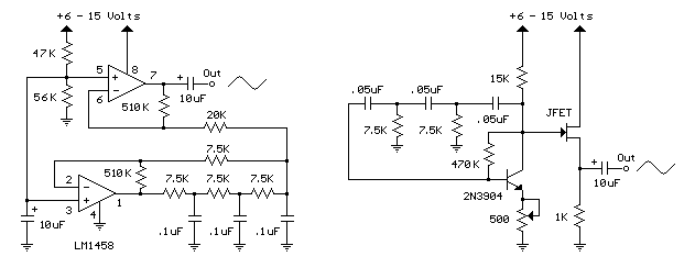
The two circuits below illustrate generating low frequency sinewaves by shifting the phase of the signal through an RC network so that oscillation occurs where the total phase shift is 360 degrees. The transistor circuit on the right produces a reasonable sinewave at the collector of the 3904 which is buffered by the JFET to yield a low impedance output. The circuit gain is critical for low distortion and you may need to adjust the 500 ohm resistor to achieve a stable waveform with minimum distortion. The transistor circuit is not recommended for practical applications due to the critical adjustments needed.
The op-amp based phase shift oscillator is much more stable than the single transistor version since the gain can be set higher than needed to sustain oscillation and the output is taken from the RC network which filters out most of the harmonic distortion. The sinewave output from the RC network is buffered and the amplitude restored by the second (top) op-amp which has gain of around 28dB. Frequency is around 600 Hz for RC values shown (7.5K and 0.1uF) and can be reduced by proportionally increasing the network resistors (7.5K). The 7.5K value at pin 2 of the op-amp controls the oscillator circuit gain and is selected so that the output at pin 1 is slightly clipped at the positive and negative peaks. The sinewave output at pin 7 is about 5 volts p-p using a 12 volt supply and appears very clean on a scope since the RC network filters out most all distortion occurring at pin 1.
Low Frequency Sinewave Generators circuit
Title: Low Frequency Sinewave Generators
electronic circuit
Source: unknown
Published on: 2007-07-21
Reads: 1866
Print version: ![]()
Other electronic circuits and schematics from Oscillators and timers
-
28 LED Clock Timer
-
Jogging Timer
-
Bedside Lamp Timer
-
Photo Timer Circuit
-
Headlights Timer
-
Low-distortion Audio-range Oscillator
-
Simple IF Signal Generator
-
Amplifier Timer
-
1KHz Sinewave Generator
-
9 Second Digital Readout Countdown Timer