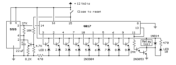
9 Second LED Timer and Relay Circuit
This circuit provides a visual 9 second delay using 10 LEDs before closing a 12 volt relay. When the reset switch is closed, the 4017 decade counter will be reset to the 0 count which illuminates the LED driven from pin 3. The 555 timer output at pin 3 will be high and the voltage at pins 6 and 2 of the timer will be a little less than the lower trigger point, or about 3 volts. When the switch is opened, the transistor in parallel with the timing capacitor (22uF) is shut off allowing the capacitor to begin charging and the 555 timer circuit to produce an approximate 1 second clock signal to the decade counter. The counter advances on each positive going change at pin 14 and is enabled with pin 13 terminated low. When the 9th count is reached, pin 11 and 13 will be high, stopping the counter and energizing the relay. Longer delay times can be obtained with a larger capacitor or larger resistor at pins 2 and 6 of the 555 timer.

9 Second LED Timer and Relay Circuit
Title: 9 Second LED Timer and Relay Circuit
electronic circuit
Source: unknown
Published on: 2007-07-21
Reads: 704
Print version: ![]()
Other electronic circuits and schematics from Oscillators and timers
-
50 Hertz LED Clock Timebase
-
9 Second Digital Readout Countdown Timer
-
28 LED Clock Timer
-
Low Voltage, High Current Time Delay Circuit
-
Precision Metronome and Pitch generator
-
Headlights Timer
-
Amplifier Timer
-
Jogging Timer
-
Low-distortion Audio-range Oscillator
-
Triangle and Squarewave Generator
