Constant Current Battery Charger
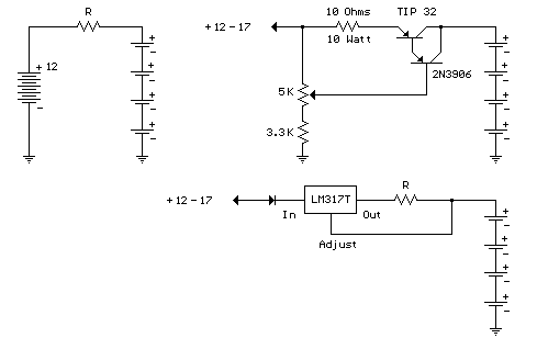
A simple method of charging a battery from a higher voltage battery is shown in the circuit below to the left. Only one resistor is needed to set the desired charging current and is calculated by dividing the difference in battery voltages by the charge current. So, for example if 4 high capacity (4000 mA hour) ni-cads are to be charged at 300 mA from a 12 volt battery, the resistor needed would be 12-(4*1.25)/0.3 = 23.3 ohms, or 22 ohms which is the nearest standard value. The power rating for the resistor is figured from the square of the current times the resistance or (0.3)^2 * 22 = 2 watts which is a standard value but close to the limit, so a 5 watt or greater value is recommended.
The circuit below (right) illustrates a constant current source used to charge a group of 1 to 10 ni-cad batteries. A 5K pot and 3.3K resistor are used to set the voltage at the emitter of the TIP 32 which establishes the current through the output and 10 ohm resistor. The emitter voltage will be about 1.5 volts above the voltage at the wiper of the pot, or about 1/2 the supply voltage when the wiper is in the downward most position. In the fully upward position the transistors will be turned off and the current will be close to zero. This yields a current range of 0 to (0.5*input)/10 or 0 to 850 milliamps using a 17 volt input. This produces about 7 watts of heat dissipation at maximum current for the 10 ohm resistor, so a 10 watt or greater rating is needed. The TIP 32 transistor will also dissipate about 7 watts if the output is shorted and needs to be mounted on a heat sink. If more than 4 cells are connected, the maximum current available will decrease and limits the current setting to about 100 milliamps for 10 cells. The usual charge rate for high capacity (4AH) 'D' cells is 300 to 400 milliamps for 14 hours and 100 milliamps for (1.2AH) 'C' or 'D' cells. For small 9 volt batteries the charge rate is 7 milliamps for 14 hours which would be difficult to set and probably unstable, so you could reduce the range to 0-20 mA by using a 750 ohm resistor in place of the 10. The charge current can be set by connecting a milliamp meter across the output (with the batteries disconnected) and then adjusting the control to the desired current, or by monitoring the voltage across the 10 ohm resistor (1 volt = 100 mA) or (1 volt = 1.33 mA using a 750 ohm resistor). The current control should be set to minimum (wiper in uppermost position) before power is applied, and then adjusted to the desired current.
The circuit (lower right) illustrates using a LM317 variable voltage regulator as a constant current source. The voltage between the adjustment terminal and the output terminal is always 1.25 volts, so by connecting the adjustment terminal to the load and placing a resistor (R) between the load and the output terminal, a constant current of 1.25/R is established. Thus we need a 12 ohm resistor (R) to get 100mA of charge current and a 1.2 ohm, 2 watt resistor for 1 amp of current. A diode is used in series with the input to prevent the batteries from applying a reverse voltage to the regulator if the power is turned off while the batteries are still connected. It's probably a good idea to remove the batteries before turning off the power.

Constant Current Battery Charger circuit
Title: Constant Current Battery Charger
electronic circuit
Source: unknown
Published on: 2007-07-21
Reads: 3856
Print version: ![]()
Other electronic circuits and schematics from Power
-
10 Amp 13.8 Volt Power Supply
-
Portable CD Player Adapter For Car
-
13.8V 20A power supply
-
Instrument panel lamp dimmer control
-
High and Low Voltage Cutout with delay and Music
-
NiCd - NiMH Charger
-
12 Volt 30 Amp PSU
-
0-50V 2A Bench power supply
-
Solid State Tesla Coil/High Voltage Generator
-
Negative Supply from single positive Supply
