
1 Watt C-Class RF Amplifier
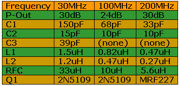
The P-Out column at the above table has been calculated when P-In (Input Power) is 13 dBm.
Title: 1 Watt C-Class RF Amplifier
electronic circuit
Source: unknown
Published on: 2005-08-27
Reads: 6422
Print version: 
Other electronic circuits and schematics from RF circuit
-
Low-Frequency Crystal Controlled Oscillator
-
2 Transistor FM Voice Transmitter
-
ZN414 Portable AM Receiver
-
FM voice transmitter for Band 2 VHF
-
Transmitter FM 45W with valve
-
Economy short-wave receiver
-
Bipolar Regenerative receiver
-
Active Antenna for Medium Wave
-
Simple Op-Amp Radio
-
6 x 6 Loop Antenna