Field-strength meter
Small, portable, anti-bag-snatching unit
Also suitable for doors and windows control
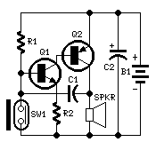
Parts:
R1____________330K 1/4W Resistor
R2____________100R 1/4W Resistor
C1_____________10nF 63V Polyester or Ceramic Capacitor
C2____________100ВµF 25V Electrolytic Capacitor
Q1____________BC547 45V 100mA NPN Transistor
Q2____________BC327 45V 800mA PNP Transistor
SW1____________Reed Switch and small magnet (See Notes)
SPKR___________8 Ohm Loudspeaker (See Notes)
B1_____________3V Battery (two A or AA cells wired in series etc.)
Device purpose:
This circuit, enclosed in a small plastic box, can be placed into a bag or
handbag. A small magnet is placed close to the reed switch and connected to the
hand or the clothes of the person carrying the bag by means of a tiny cord.
If the bag is snatched abruptly, the magnet looses its contact with the reed
switch, SW1 opens, the circuit starts oscillating and the loudspeaker emits a
loud alarm sound.
The device can be reverse connected, i.e. the box can be placed in a pocket and
the cord connected to the bag.
This device can be very useful in signalling the opening of a door or window:
place the box on the frame and the magnet on the movable part in a way that
magnet and reed switch are very close when the door or window is closed.
Circuit operation:
A complementary transistor-pair is wired as a high efficiency oscillator, directly driving a small loudspeaker. Low part-count and 3V battery supply enable a very compact construction.
Notes:
- The loudspeaker can be any type, its dimensions are limited only by the box that will contain it.
- An on-off switch is unnecessary because the stand-by current drawing is less than 20ВµA.
- Current consumption when the alarm is sounding is about 100mA.
- If the circuit is used as anti-bag-snatching, SW1 can be replaced by a 3.5mm mono Jack socket and the magnet by a 3.5mm. mono Jack plug with its internal leads shorted. The Jack plug will be connected with the tiny cord etc.
- Do not supply this circuit with voltages exceeding 4.5V: it will not work and Q2 could be damaged. In any case a 3V supply is the best compromise.
Title: Field-strength meter
electronic circuit
Source: www.redcircuits.com
Published on: 2005-02-10
Reads: 875
Print version: ![]()
Other electronic circuits and schematics from Security and other sensors and detectors
-
Factory Siren
-
Electronics Telephone Talking Circuit
-
Sound Operated Switch
-
Dew sensor
-
Infrared beam barrier/ proximity sensor
-
Room Noise Detector
-
4 in 1 Burglar Alarm
-
Capacitive Sensor
-
Light switch
-
A simple electronic buzzer