Line Robot
 Recently
many kind of robot contests have being opened and some interesting reports of
the challenge are found on the web. The Line Following is a kind of the robot
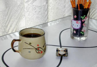
contests to vie running speed on the line. I build a tiny line following robot
which can run on the desk, moving the key board aside will do. It is for only
a personal toy reduced its size less than one fifth compared to typical line
following robots, not in formura. But I believe that it is suitable for home
use in the small Japanese houses said that rabbit burrow...(^_^;. Of course
I have also no time to take part in the robot contests :-(
Recently
many kind of robot contests have being opened and some interesting reports of
the challenge are found on the web. The Line Following is a kind of the robot
contests to vie running speed on the line. I build a tiny line following robot
which can run on the desk, moving the key board aside will do. It is for only
a personal toy reduced its size less than one fifth compared to typical line
following robots, not in formura. But I believe that it is suitable for home
use in the small Japanese houses said that rabbit burrow...(^_^;. Of course
I have also no time to take part in the robot contests :-(About Line Follower
The line follower is one of the self operating robot that follows a line that drawn on the floor. The basic operations of the line following are as follows:
- Capture line position with optical sensors mounted at front end of the robot. Most are using several number of photo-reflectors, and some leading contestants are using an image sensor for image processing. The line sensing procss requires high resolution and high robustness.
- Steear robot to track the line with any steearing mechanism. This is just a servo operation, any phase compensation will be required to stabilize tracking motion by applying digital PID filter or any other servo argolithm.
- Control speed according to the lane condition. Running speed is limited during passing a curve due to friction of the tire and the floor.
There are two line styles, white line on the black floor and black line on the white floor. Most contest are adopting the first one in line width of between 15 and 25 millimeters.
Hardware
Mechanics
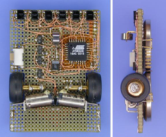
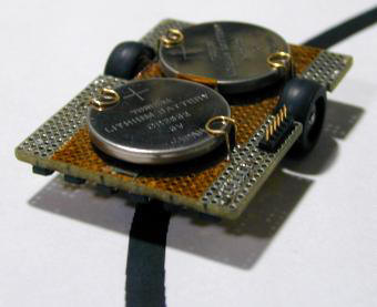
Right image shows bottom view and side view of the built line following robot. All mechanical and electrical parts are mounted on a proto board, and it also constitutes the chasis.
The line following robot is upheld in three points of two driving wheels and a free wheel. The driving wheels are made with a 7 mm dia ball bearing and a rubber tire. The free wheel is a 5 mm dia ball bearing attached loosely. To drive driving wheels, two tiny vibration motors that used for cellular phone, pager or any mobile equipment are used. Its shaft is pressed onto the tire with a spring plate, the output torque is transferred to the wheels.
The steearing mechanism is realized in differential drive that steear the robot by difference in rotation speed between the left wheel and the right wheel. It does not require any additional actuator, only controling the wheel speed will do.
Electronics
| Controller | ATmega8 (Atmel) |
| Line sensor | Six photo-reflectors |
| Power supply | Two CR2032 lithium cells (One is for controller, the other is for motors) |
| Motor | Two micromotors for left wheel and right wheel |
| Dimensions | 45(L), 33(W), 12.5(H) [mm] |
| Weight | 15 grams (Body:8g, Cells:7g) |
| Performance | 53 centimeter per second at oval course |
An Atmel ATmega8 is used for the controller and it is powered by a lithium coin cell. The other lithium coin cell is for only motors. Separating the power supply into two cells is to avoid accidental reset of the microcontroller due to voltage dip by motor start current. Six photo-reflectors are mounted at front end of the chasis. They sense reflection rate of the floor under them. Motors are driven in PWM to control rotation speed lineary. The latest circuit diagram is here.
Software
Using photo-reflectors
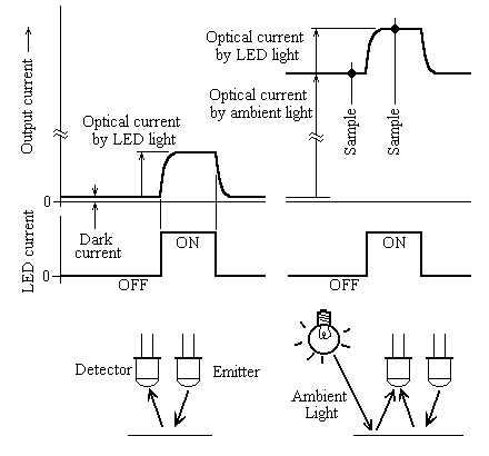
To detect a line to be followed, most contestants are using two or more number of poto-reflectors. Its output current that proportional to reflection rate of the floor is converted to voltage with a resister and tested it if the line is detected or not. However the threshold voltage cannot be fixed to any level because optical current by ambent light is added to the output current like the image shown right.
Most photo-detecting modules for industrial use are using modurated light to avoid interference by the ambient light. The detected signal is filtered with a band pass filter and disused signals are filtered out. Therefore only the modurated signal from the light emitter can be detected. Of course the detector must not be saturated by ambient light, this is effective when the detector is working in linear region.
In this project, pulsed light is used to cancel ambient light. This is suitable for arraied sensors that scanned in sequence to avoid interference from next sensor. The microcontroller starts to scan the sensor status, sample an output voltage, turn on LED and sample again the output voltage. The difference between the two samples is the optical current by LED, output voltage by the ambient light is canceled. The other sensors are also scanned the same avobe in sequence.
Signal processing of line detection
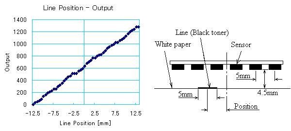
Right image shows the actual line posisiton vs detected line position in center value of 640. The microcontroller scans six sensors and calcurates the line position by output ratio of two sensors near the line. Thus the line position can be detected lineary with only six sensors. All the sensor outputs are captured as analog value that proportioning to reflection ratio, and the sensitivity have variety between each one of them. In this system, to remove the variations from the outputs, calibration parameters for each sensor can be held into non-volatile memory. This can be done with online mode. The microcontroler enters the online mode when an ISP cable is attached, and it can be controlled with a terminal program in serial format of N81 38.4kbps. S1 command monitors sensor values, and S2 command calibrates variation of sensor gain on the reference surface (white paper). The ATmega8 must be set to 8MHz internal osc.
Tracking control
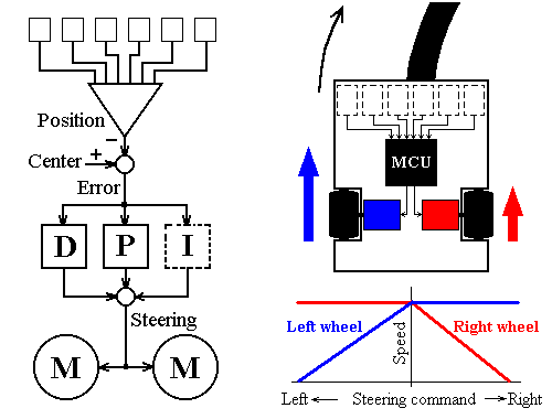
The line position is compeared to the center value to be tracked, the position error is processed with Proportional/Integral/Diffence filters to generate steering command. The line folloing robot tracks the line in PID control that the most popular argolithm for servo control.
The proportional term is the commom process in the servo system. It is only a gain amplifire without time dependent process. The differencial term is applied in order to improve the responce to disturbance, and it also compensate phase lag at the controled object. The D term will be required in most case to stabilize tracking motion. The I term is not used in this project from following resons. The I term that boosts DC gain is applied in order to remove left offset error, however, it often decrease servo stability due to its phase lag. The line following operation can ignore such tracking offset so that the I term is not required.
When any line sensing error has occured for a time due to getting out of line or end of line, the motors are stopped and the microcontroller enters sleep state of zero power consumption.
Notes
- Development diary [Ja]
- Circuit diagram
- Firmware May 23, 2004
- Following motion
with only P control
This is a video file of line following motion with only P control. The servo system oscllated. - Following motion
with P and D controls
Adding D control could improve the servo stability. The robot follows the line correctly. Therefore the servo parameter must be optimized for mechanical characterristics to improve the tracking stability.
Title: Line Robot
electronic circuit
Source: http://elm-chan.org/
Published on: 2005-06-26
Reads: 6803
Print version: ![]()
Other electronic circuits and schematics from Robotics
-
IR Detector for Robotics
-
90S2313 AVR Robot Board
-
RF Modem Robotics Project
-
5-motor walker circuit
-
Walker Robot
-
12-way Input/Output Interface