RF Modem Robotics Project
Rob Arnold
Robot.guy@gte.net
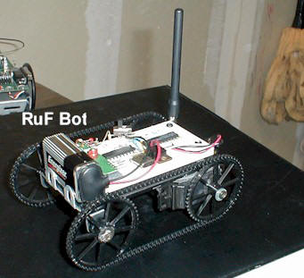
Ruf Bot uses the TWS 434 RF system
RF is just way too cool not to use in your designs. But if you're a newbie like me it is difficult to successfully build solid RF transmitters and receivers. When I started out I didn't realize that the larger breadboard I was working off of was causing a lot of the signal deviance because the metal traces on the breadboard worked like small capacitors and changed my circuit dynamics. So after much research I found the Reynolds Electronics RWS and TWS 434 RX/TX pair. I looked into a similar product by MING Microsystems and Radioshack but the Reynolds were superior in performance, cost and ease of use. So with that and two PIC 16F84's I started working on my serial RF link from my control interface (Joystick) to my robot.
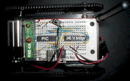
Top view of the robot showing construction on a small breadboard
A schematic of this circuit
I found that the TX/RX pair and the serial communication built into the PICBasic programming language for my PIC's worked very well together. I wasn't sure how well the timing would work using Asynchronous Serial communication at 9600 baud, I expected some problems at this higher speed but in testing found very little error. The actual programming couldn't be easier since it is written in Basic and uses premade serial communication routines. I simply read the position of the Potentiometer in the joystick using the PICBasic 'POT' command and put the result in memory location 'B0'. From there using the 'SEROUT' command I sent the contents of 'B0' to pin 6 of the TWS 434 transmitter. On the receiver end I use the 'SERIN' command and read the incoming data from pin 3 on the RWS 434 and put the result in 'B0'. The value in 'B0' directly correlates to joystick position, above 150 is right, below 106 is left, and in between is center. By using these numbers I can define a deadzone.
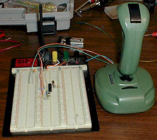
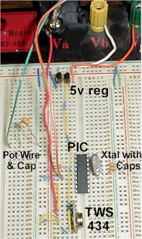
The PIC reads and transmits joystick information
At this point implications are easy to see. From the numbers transmitted we can determine direction (left, right, etc) and also extent, or how far left and how far right. With this information speed control can be introduced. The further the number from 128 (center) the more speed is applied. In this example I used the pins on PORTA of the PIC to control the motor direction and no speed control is used. Since our serial data is 10 bits in length (1 start bit, 8 data bits, 1 stop bit) we can send 960 commands to the receiving PIC in one second. Not bad for under $20 in parts. Using antennas made for 900Mhz cordless telephones I was able to get a range of 350 feet outdoors, and when I boosted transmitter power slightly past 12 volts (not recommended) I achieved a distance of 500 feet.
Note: I used the linear output on the reciever because I wanted to see how much noise it would take to distort the signal before it became useless. To my suprise the signal strength (at 500 feet) dropped off before any noise on the frequency caused problems.
The following code snippets show how easy it is to work these parts into your system.
TX CODE:
symbol trisb = 134
symbol trisa = 133
symbol portb = 6
symbol porta = 5
poke trisa, 1
low 1			'use this line if enable pin on 245 is not grounded.
input 0
start:
B0 = 0
pot 0,25,B0
serout 1,n9600,(B0)
goto start
left:
serout 1,n2400,(255)
goto start
right:
serout 1,n2400,(1)
goto start
end
RX CODE:
symbol trisb = 134
symbol trisa = 133
symbol portb = 6
symbol porta = 5
poke trisa ,0
poke porta ,0
low 0
input 1
start:
B0 = 0
serin 1,n9600,B0
if B0 > 150 then right
if B0 < 106 then left
goto stop
right:
poke porta, 6
goto start
left:
poke porta, 9
goto start
stop:
poke porta, 0
goto start
end
Title: RF Modem Robotics Project
electronic circuit
Source: http://www.seattlerobotics.org
Published on: 2005-06-26
Reads: 3564
Print version: ![]()
Other electronic circuits and schematics from Robotics
-
Line Robot
-
12-way Input/Output Interface
-
IR Detector for Robotics
-
5-motor walker circuit
-
Walker Robot
-
90S2313 AVR Robot Board