90S2313 AVR Robot Board
The Atmel AVR series are very good microcontrollers with quite a rich instruction set, rich enough that lots of folks have good compilers for them so we don't have to learn their assembler. A very rich compiler available is the BASCOM/AVR compiler from MCS Electronics. I've used this compiler for prototyping the software on my 90S2313 robot board for two reasons: One, It has a very rich command syntax; Two, its free in its demo version! The demo version only supports 2K of instruction memory, other than that it is completely uncrippled. The 90S2313 has 2K of instruction memory - See the pattern?
I designed this board to use my IRPD chip and my Serial Servo Chip to handle the "eyes" and the "legs" of this robot board respectively. Because the 2313 does not have A2D capability, I also added the SPI based MCP3202 dual channel A2D chip. Finally, because I like to have some kind of debug capability, I added the MAX232 circuit to the hardware UART on the 2313 chip.
Currently all that I have done is make sure that the board is fully functional. Note that BASCOM/AVR now has the ability to control up to 8 servos in the background - My SSC chip will take up less system overhead, but with this new capability, it really isn't needed. However, note that the SSC chip uses one I/O line and controls 4 servos.
Below is the test code for the board. It tests out the servo by using the software UART on an arbitrary output pin, then tests the IRPD (waving hands in front of it a bit), then it blinks an LED on a port to show single bit output and finally grabs A2D input from the MCP3202 - The A2D ports are designed so that I can just stick a trim pot into them and twidling it. Incidentally, it also checks out the RS232 connection to the PC by printing to it. So this test software shows how to do serial, digital and SPI input/output! Very nice. Here is a link to the actual file.
The board is programmed with a 5 pin dongle that plugs onto the board and is connected to the PeeCee parallel port in the BASCOM/AVR configuration. See the Dontronics Newbie AVR site for info on this layout - He has a wonderful introduction to AVR and BASCOM/AVR there. While you're there, check out his DT006 experimenters board, very cool.
'--------------------------------------------------------------
' file: Test2313.BAS
' demo: Test2313, HEX
' DLC 5/28/2001
'--------------------------------------------------------------
Dim A As Byte , B1 As Byte , C(3) As Byte
Dim L As Bit
Config Portd = &B0010010
'PD0 = RxD, Input
'PD1 = TxD, Output
'PD2 = IRPDR, Input
'PD3 = IRPDL, Input
'PD4 = LED, Output
'PD5,6 = Inputs
Print "Testing TTT 90S2313 Robot board"
Print "Now working the SSC chip"
'PortB.3
Open "comb.3:2400,8,n,1" For Output As #1
Printbin #1 , 01
Wait 1
Printbin #1 , 31
Wait 1
Printbin #1 , 63
Close #1
Print "Now checking IRPD"
For A = 1 To 10
B1 = Pind And &H0C
Rotate B1 , Right , 2
Print B1
Wait 1
Next A
Print "Toggling the LED Now"
For A = 1 To 10
Portd.4 = Not Portd.4
Waitms 200
Next A
Print "Now checking out the MCP3202"
'Configure for SPI
Config Spi = Soft , Din = Portb.6 , Dout = Portb.5 , Clock = Portb.7
Config Pinb.4 = Output
Portb.4 = 0
Spiinit
'Tell 3202 to do a reading
A = &B00001100
For B1 = 1 To 20
Portb.4 = 0
Spiout A , 1
Spiin C(1) , 2
Portb.4 = 1
C(3) = C(1)
Shift C(1) , Right , 4
Shift C(2) , Right , 4
Shift C(3) , Left , 4
C(2) = C(2) Or C(3)
Print C(1) ; " " ; C(2)
Wait 1
Next B1
Print "Completed"
End
Here's the Schematic for the board
Click to make it larger.
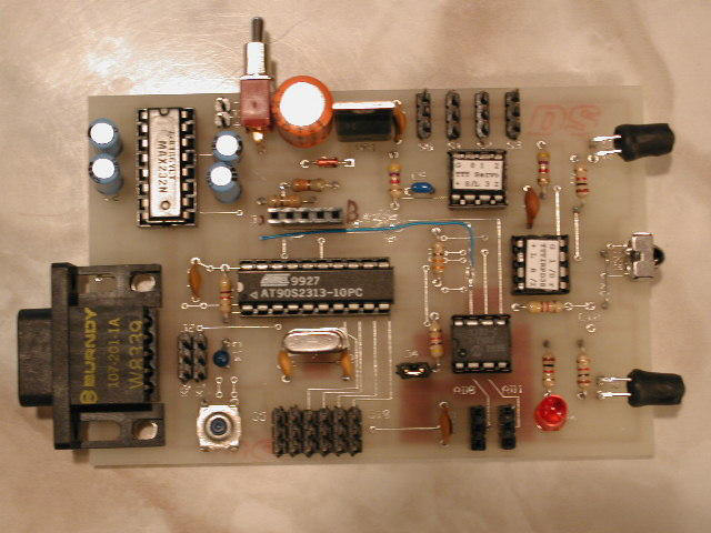
Here's what the prototype board looks like fully built
Title: 90S2313 AVR Robot Board
electronic circuit
Source: unknown
Published on: 2005-06-26
Reads: 4705
Print version: ![]()
Other electronic circuits and schematics from Robotics
-
12-way Input/Output Interface
-
5-motor walker circuit
-
IR Detector for Robotics
-
RF Modem Robotics Project
-
Walker Robot
-
Line Robot