Walker Robot
 Note:
This is just a quick page to get some photos up. Tons more info and schematics are
coming soon.
Note:
This is just a quick page to get some photos up. Tons more info and schematics are
coming soon.
Video of vWalker walking! (15 seconds - 1.4MB)
Overview:
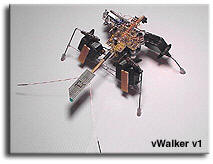
This is vWalker v1. The "v" standing for V, as in five. It is a five motor walker that goes towards light and avoids obstacles. The goal was to create a walker that could navigate over rough complex terrain while seeking out the brightest source of light. The base controller for the walker is four master/slave linked bicores. All of the other circuits take input from sensors and modify the signal coming out of the bicores to make the walker backup, turn, and seek light.
Operation:
Currently vWalker has five possible states... Walk forward lifting the front legs Walk forward lifting the back legs Walk backwards Stray to the right ~2' turn radius Stray to the left ~2' turn radius
Here is the basic layout:
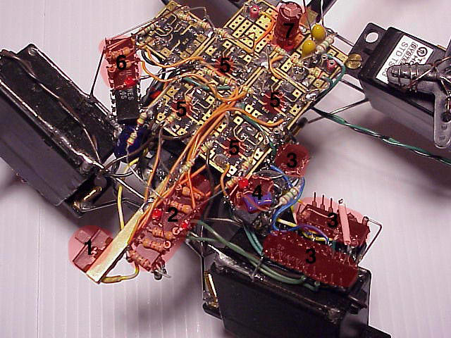
1. On-Off switch
2. Reversers for turning the walker left and right.
3. The part used for controlling light seeking
4. A bicore. Not used for anything at this point.
5. Bicores that control the legs.
6. Reverser that causes the walker to back-up
7. Timer capacitor for backing up.
8. Battery Changer (not visible)
vWalker schematic:
Notes: The only thing not show are the motor drivers. I used two sets of three 74AC240 inverters in parallel to drive each servo. Any driver will work so just swap out the (M) with your driver of choice. Here's what mine looked like...
Wilf Rigter's Description of vWalker (much thanks to Wilf):
Here is a description of the vWalker circuit operation. Understanding how the circuit works should help you with troubleshooting.
AN OVERVIEW OF THE vWALKER-V1 ELECTRONICS by Wilf Rigter - JAN/2001
This description of operation must be used with the schematic in http://www.beam-online.com/Robots/vwalker1/index.html of Ian's vWalker v1. Currently this schematic shows no pin numbers for the 240 inverters but identifies the inverters with a letter as one of a group of 4 inverters which are tri-state enabled by the same control pin. Each 74HC/AC240 chip has two groups of four inverters and two tri-state enable pins. Some groups are permanently enabled by grounding the control pin. Other groups of inverters are turned on or off with the tri-state enable pin for reverser and control circuits. In some cases, only one or two inverters of a group of four is used, while the others are left unused. This is probably a result of the use of "tile" circuits which are easy to connect together to form a functional circuit but this design method is often inefficient in making full use of the available resources. In this description, the group letter followed by a number in brackets is used to identify and indicate the number of inverters used for a particular part of the circuit.
The whole vWalker design consists of several sections:
I) The light detector uses inverters from group F(2),J(2),K(1),L(1) and one 2 input AND gate to generate the enable signals which control 3 output states: a. turn left, b. turn right, c. go straight
II) Two master bicores use inverters from groups B(2) and C(2) which are coupled with the 7.2M resistor to so that they will oscilate in quadrature with their waveforms overlapping by 25%. These are connected to the motor drivers (Ian used 6 74AC240 inverters for each motor) which control the two rear legs.
III) Two front motor slave bicores use inverters from groups D(2) and E(2) with timing components that delay the slave bicore output by about 25%. These are connected to the front leg motor drivers (6 inverters for each motor).
IV) Two front motor reverser circuits and LED indication use inverters from groups H(3), I(3) and are connected between the outputs of each of the master bicores (rear legs) and the slave bicores (front legs) to control turning with enable signals from the light detector circuit. When both reversers are turned off, the walker moves straight.
V) One waist slave bicore circuit uses inverters from group A(2) to control the waist motor driver (using six 240 inverters). In fact (as far as I know) this slave bicore is not required at all (see VI).
VI) The waist inverter uses inverters from group G(2) and is connected between one output of each of the two master bicores and the waist slave bicore circuit in V). As far as I know the output of the reverser should be connected directly to the waist motor drivers. The waist reverser circuit is enabled with one of two tactile switches triggered by collision.
VII) The power supply consists of a 4.8V NiCd battery with an on off switch and a rectifier is included for recharging the battery pack without removing it from the walker.
DETAILS OF OPERATION
The Light Detector
The light detector uses two photodiodes as a "photo bridge" to sense when the light level is balanced or unbalanced on two photodiodes. The 2 photodiodes are connected reverse biased in series across the power supply with the midpoint acting as a voltage divider. It uses 2 inverters of group F connected in series to give complimentary steady state outputs when the PD are unbalanced. Both inverter outputs are pulsing at high frequency when the light on the PDs is balanced and the photo bridge midpoint is near the switching threshold of the first inverter input. I suggest connecting a small cap (eg 0.001uf) from the output of the second inverter back to the midpoint of the PD bridge to lower the frequency of oscillation and reduce power consumption. The ouputs of inverters F are connected to the enable pins of inverters K and L. The outputs of inverters K and L are used to charge two 3uf capacitors (observe polarity) at the inputs of the NAND gate to +V when they turn on even if the output are pulsing. Once K and L turn off, the capacitors discharge through the 1.6M resistors. If both K and L are pulsing when the light is balanced, the AND gate inputs are both positive and the output of the AND gate is used to disable the J inverters which control the turning reversers in section IV). When the light is unbalanced, one F inverter is high and one is low and consequently one input of the AND gate will go low. That causes the AND output to go low and the J inverters are enabled and control the turning by enabling the respective reverser circuit in IV)
The Master Bicores
The master bicores generate the two sets of central pattern signals which are phase locked in quadrature with the 7.2M coupling resistor. Interestingly, this method of phase locking relies on the fact that normally both bicores are oscillating at nearly the same frequency but with one slightly faster than the other. This faster bicore will "pull" the frequency of the slower bicore and effectively "enslave" that master bicore. However with perfectly matched components the two could switch roles and while frequency locked, they would wander back and forth in phase relationship!
The Reversers
The reversers are sometimes called Mat Muxes and their function is to control the phase inversion of pairs of signals. This is done by routing the signals through one of two parallel paths
a) inverted through a tristate inverter or
b) non-inverted through a resistor when the tristate inverter is disabled.
These pairs of signals are generally the complementary outputs from a master bicore and the reversers are used to control turning. The waist reverser however uses one output each from the two master bicores and when enabled by collision switches, changes the phase angle of the waist rotation. The waist determines when the legs are lowered on the floor, either on the front or the rear stroke of the legs and therefore determines the forward and reverse direction.
The Slave Bicores
The slave bicores delay the phase angle of the front legs with respect to the rear legs which are controlled by the master bicores. The reversers between the master and slave bicores determine whether the front and rear legs (on opposite corners) are moving in the same or opposite direction when the legs are on the ground. This causes the legs to both move forwards or backwards together or to rotate the body of the walker slightly with each step of those legs until the light level is balanced on the two PDs. The operation of the reversers and the light detector is indicated with LEDS controlled by spare inverters. Although not show in Ian's schematic make sure you add 1K-10K resistors in series with each LED.
The Power Supply
The last part is the 4.8V NiCd battery pack designed to be used with a wall type charger. A switch is included to turn the unit off when not in use.
An LED in series with 10K resistor indcates when the charger is ON.
On final note: All inverters which are not used should have their inputs grounded.
Title: Walker Robot
electronic circuit
Source: http://beam-online.com
Published on: 2005-06-26
Reads: 4515
Print version: ![]()
Other electronic circuits and schematics from Robotics
-
RF Modem Robotics Project
-
IR Detector for Robotics
-
5-motor walker circuit
-
90S2313 AVR Robot Board
-
Line Robot
-
12-way Input/Output Interface