TransistorsElectronics guide > Transistors
In previous chapters we’ve looked at semiconductors, spending some time on diodes (the simplest semiconductor device) and taking brief glimpses of integrated circuits. It’s the turn of the transistor now to come under the magnifying glass — perhaps the most important semiconductor of all.
You don’t need many components this chapter, just a handful of resistors:
- 1 x 100 kΩ
- 1 x 220 kΩ
- 1 x 47 kΩ miniature horizontal preset
and, of course, one transistor.
The type of transistor you need is shown in Photo 8.1 and is identified as a 2N3053.
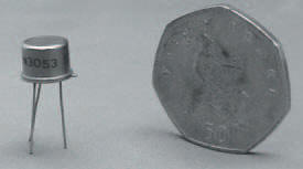
Photo 8.1 A transistor next to a UK fifty pence piece
You’ll see that the transistor has three terminals called, incidentally, base, collector and emitter (often shortened to B, C and E). When you use transistors in electronic circuits it is essential that these three terminals go the right way round. The 2N3053 transistor terminals are identified by holding the transistor with its terminals pointing towards you from the body and comparing the transistor’s underneath with the diagram in Figure 8.1. The terminal closest to the tab on the body is the emitter, then in a clockwise direction are the base and the collector.
Other transistor varieties may have different body types so it’s important to check with reference books or manufacturer’s data regarding the transistor terminals before use. All 2N3053 transistors, however, are in the same body type — known as a TO-5 body — and follow the diagram in Figure 8.1.
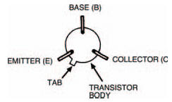
Figure 8.1 How to recognise the location of the base, emitter and collector connections on a common transistor body
For the previous two chapters, we’ve looked closely at diodes — the simplest of the group of components known as semiconductors. The many different types of diodes are all formed by combining doped layers of semiconductor material at a junction. The PN junction (as one layer is N-type semiconductor material and the other layer is P-type) forms the basis of all other semiconductor-based electronic components. The transistor — the component we’re going to look at now — is, in fact, made of two PN junctions, back to back. Figure 8.2 shows how we may simply consider a transistor as being two back-to-back diodes, and we can verify this using our multimeter to check resistances between the three terminals of a transistor: the base, emitter and collector.
To do the experiment, put a transistor into your breadboard, then use the meter to test the resistance between transistor terminals. Using our brains here (I know it’s hard) we can work out that if there are three terminals there must be six different ways the meter leads can connect to pairs of the terminals. Table 8.1 lists all six ways, but the results column is left blank for you to fill in as you perform the experiment.
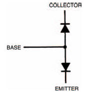
Figure 8.2 A symbol for a transistor considered as two diodes, back to back
It’s not necessary for you to measure the exact resistance obtained between terminals, it’s sufficient just to find out if the resistance is high or low.
Take note
One final point before you start — the casing of the transistor body (sometimes called the can) is metal and therefore conducts. When you touch the meter test probes to the transistor terminals make sure, therefore, they don’t touch the can. It’s all too easy to do without realising you’ve got a short circuit which, of course, gives an incorrect result. The can of a TO-5 bodied transistor such as the 2N3053 is also electrically connected to the transistor’s collector, so be careful!
Table 8.1 Six different ways to connect the meter leads
Your results should show that low resistances occur in only two cases, indicating forward current flow between base and emitter, and base and collector. This corresponds as we should expect to the diagram of Figure 8.2.
<< Practically there