Tough switch
General Description
A touch switch is an electronic device that enables us to control a circuit by simply
touching a sensor. Smart Kit 1005 is a very easy project to built and will make
you the proud owner of a magic switch that will respond to the slightest touch of
your hand on its sensitive plates.

Technical Specifications - Characteristics
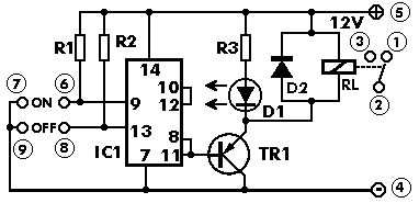
Supply voltage: 12 VDC
Max. current:30 mA
Relay rating: 250 V/2 A
How it Works
The circuit as you can see from its diagram is very simple and only uses 8 components.
The heart of the circuit is the IC CD 4011 that is connected as a FLIP-FLOP. Pins
9 and 13 of the IC are the В«SETВ» and В«RESETВ» contacts of the FLIP-FLOP. The IC is
of the CMOS type and requires a very low current to in its gates to control it.
This high sensitivity of the circuit makes the touch operation possible. The two
gates are held at logic state В«1В» continuously by means of the two resistors R1
and R3 that connect them to the positive supply rail. These resistors have a very
large resistance of 10 Mohm. If we now touch a set of contacts the skin resistance
closes the circuit between the corresponding gate and the negative supply rail.
The skin resistance for small areas of the skin is normally much lower than 10 Mohm
and the gate is effectively brought to logic condition В«0В» which makes the FLIP-FLOP
change state. For any given state of the FLIP-FLOP touching the corresponding set
of contacts will make the circuit to reverse its state of balance and in effect
toggle the switch. As a switch is used a relay driven by a transistor which is driven
from the out put of the FLIP-FLOP.
Construction
First of all let us consider a few basics in building electronic circuits on a printed
circuit board. The board is made of a thin insulating material clad with a thin
layer of conductive copper that is shaped in such a way as to form the necessary
conductors between the various components of the circuit. The use of a properly
designed printed circuit board is very desirable as it speeds construction up
considerably and reduces the possibility of making errors. Smart Kit boards also
come pre-drilled and with the outline of the components and their identification
printed on the component side to make construction easier. To protect the board
during storage from oxidation and assure it gets to you in perfect condition the
copper is tinned during manufacturing and covered with a special varnish that protects
it from getting oxidised and makes soldering easier. Soldering the components to
the board is the only way to build your circuit and from the way you do it depends
greatly your success or failure. This work is not very difficult and if you stick
to a few rules you should have no problems. The soldering iron that you use must
be light and its power should not exceed the 25 Watts. The tip should be fine and
must be kept clean at all times. For this purpose come very handy specially made
sponges that are kept wet and from time to time you can wipe the hot tip on them
to remove all the residues that tend to accumulate on it.
DO NOT file or sandpaper a dirty or worn out tip. If the tip cannot be cleaned,
replace it. There are many different types of solder in the market and you should
choose a good quality one that contains the necessary flux in its core, to assure
a perfect joint every time.
DO NOT use soldering flux apart from that which is already included in your solder.
Too much flux can cause many problems and is one of the main causes of circuit malfunction.
If nevertheless you have to use extra flux, as it is the case when you have to tin
copper wires, clean it very thoroughly after you finish your work. In order to solder
a component correctly you should do the following:
Clean the component leads with a small piece of emery paper. - Bend them at the correct distance from the component body and insert the component in its place on the board. You may find sometimes a component with heavier gauge leads than usual, that are too thick to enter in the holes of the p.c. board.
In this case use a mini drill to enlarge the holes slightly. Do
not make the holes too large as this is going to make soldering difficult afterwards.
Take the hot iron and place its tip on the component lead while holding the end of the solder wire at the point where the lead emerges from the board.
The iron tip must touch the lead slightly above the p.c. board.
When the solder starts to melt and flow wait till it covers evenly the area around the hole and the flux boils and gets out from underneath the solder. The whole operation should not take more than 5 seconds. Remove the iron and let the solder to cool naturally without blowing on it or moving the component. If everything was done properly the surface of the joint must have a bright metallic finish and its edges should be smoothly ended on the component lead and the board track. If the solder looks dull, cracked, or has the shape of a blob then you have made a dry joint and you should remove the solder (with a pump, or a solder wick) and redo it.
Take care not to overheat the tracks as it is very easy to lift them from the board and break them.
When you are soldering a sensitive component it is good practice to hold the lead
from the component side of the board with a pair of long-nose pliers to divert any
heat that could possibly damage the component.
Make sure that you do not use more solder than it is necessary as
you are running the risk of short-circuiting adjacent tracks on the board, especially
if they are very close together. - After having finished your work cut off the excess
of the component leads and clean the board thoroughly with a suitable solvent to
remove all flux residues that still remain on it.
The switch only has eight components and its construction is very easy even for
the most inexperienced. As usual construction must start from the least sensitive
to heat components, which in this case are the IC socket and the pins. After soldering
the pins and the socket, make the two jumper connections that are marked on the
component side of the board, solder the relay in its place and continue with the
transistor the diode and the LED. Once everything is in its place clean the board
very well from flux residues and check it for short circuits and possible mistakes.
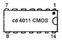
Then, place the IC in its socket. The IC is of the CMOS family and
should be
handled with great care as it can be damaged very easily from static discharges.
Avoid touching its pins and keep your body and the circuit board grounded during
insertion. You should also take care not to bent any pins underneath the IC body
during this operation.

Now connect the points marked + & - on the board with 12 VDC and touch lightly the
set of contacts marked В«ONВ». You should hear the clicking of the relay and the LED
should light up. (In case the LED turns on at power up then touch the other set
of contacts that are marked В«OFFВ».) Touching the contacts marked В«OFFВ» will turn
the LED off and the relay should be released. It is up to you
to connect any device you want to control with the touch switch but please remember
that you should not exceed the power rating of the relay which is 250 V/2 A.
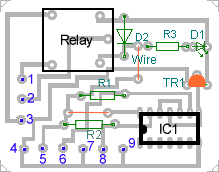
Dimensions 5,5cm x 4,2cm
If it does not work
Check your work for possible dry joints, bridges across adjacent tracks or soldering
flux residues that usually cause problems.
-Check again all the external connections to and from the circuit to see if there
is a mistake there.
See that there are no components missing or inserted in the wrong places.
Make sure that all the polarised components have been soldered the right way round.
Make sure the supply has the correct voltage and is connected the right way round
to your circuit.
Make sure that you have inserted the IC in its socket correctly and that you have
not bent any pins during insertion.
Check your project for faulty or damaged components.
Parts
R1:...........10MOhm 1/4 W D2:...........1N4148 diode
R2:...........10MOhm 1/4 W TR1:.........BC558 PNP Transistor - BC327
R3:........... 1KOhm 1/4 W IC1:..........CD4011 CMOS IC
D1:........... Led red RL1:..........12V relay rated at 250 V / 2A
Title: Tough switch
electronic circuit
Source: smartkit
Published on: 2005-02-10
Reads: 1129
Print version: ![]()
Other electronic circuits and schematics from Security and other sensors and detectors
-
IR transceiver 1.0
-
Electronics Telephone Talking Circuit
-
Digital Remote Thermometer
-
Heating System Thermostat
-
4 in 1 Burglar Alarm
-
Light Barrier Detector
-
Metal Detector
-
4 channel Telemetry System
-
A simple electronic buzzer
-
IR Remote Control Extender Circuit