4 channel Telemetry System
Basic Description
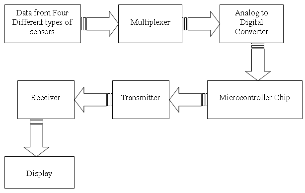
Basic Idea for the the project is to transmit the data from one point to another, this transmission may be wireless or with wire, well wireless is more enhance technology than with-wire transmission so we adopted wireless transmitting and receiving data. This project transmits 4 types of data by different types of sensors. They include Temperature sensor, Fuel level Sensor, Pressure sensor and rpm sensor. These all sensors have analog output in the form of voltages so we have to convert it into digital data then we will able to transmit.
Why convert analog into digital data?

Well we converted analog data into digital data. Why? Because four different types of data are being transmitted trough one channel so multiplexing is required. Due to this we used a digital switch which multiplexed the four data and convert it into digital form one by one. Note: Transmitter range 12-15 feet
Data transmission

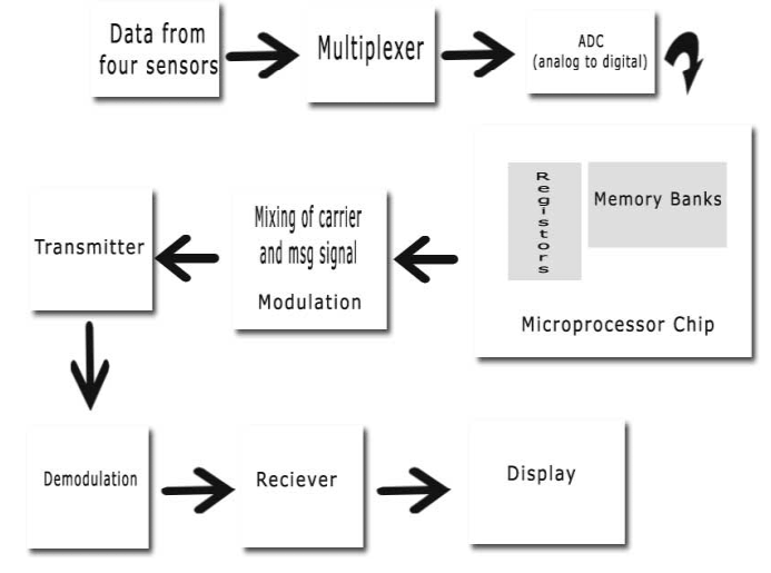
Block Diagram shows the data Transmission of the message signal by some modulation process.
Data Receiving

After receiving Data from receiver, it will be demodulate after the process of demodulation we will get the real data which we required and we want to transmit and we can easily display it. Note: Transmitter Works on 98 MHz
Function Block Diagramm
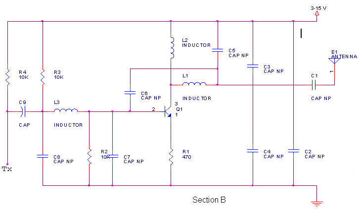
Circuit Diagram
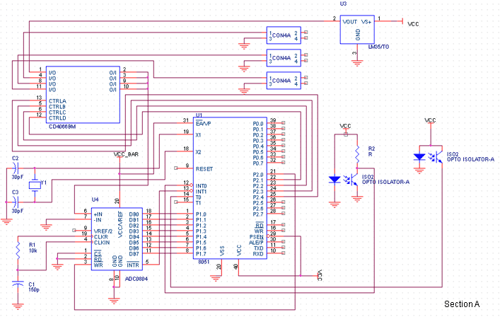
Circuit Description
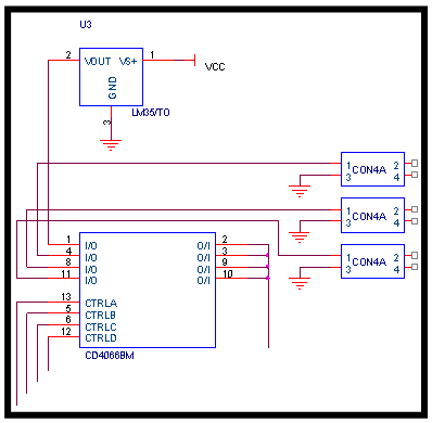
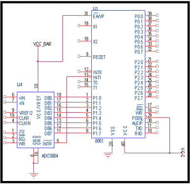
| This is the circuit for the project Section A of the
circuit is receiving signals from the four sensors, here we use an IC M4066
this is just an analog as well as digital switch which have three four input/outputs
having a controlling signal pin which controls the data flow in the circuit.
This controlling is made by the pins of microcontroller with ports 2.1-2.4.
After entering data into microcontroller it will transmit by transmitter. |
 |
 |
|
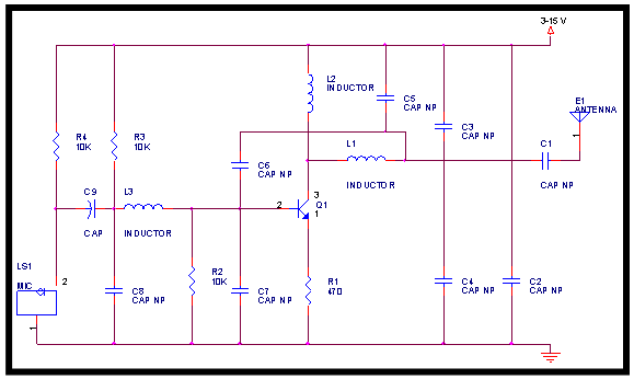
Data Flow Diagram
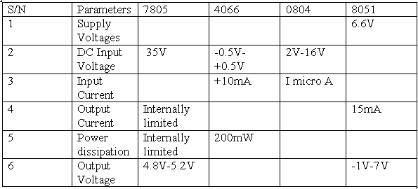
Data Sheet
Source code:
Calculations for downlink
1. Free space path loss at distance 2km is 78.285dB
2. Frequency 98 MHz
3. Effective Isotropic radiated Power is 9dB
4. Antenna gain is 10
5. radiated power is 0.8W
6. Carrier to noise ratio C/N = 159.35dB can’t calculate satellite gain and additional atmospheric losses because we haven’t much knowledge about it.
What Next??
1. increase the range up to 2Km
2. output voltage at receiving side be 5V
3. What type of antenna can be used for transmission and receiving data?
4. What type of amplifier will use for transmitting and receiving power?
5. If less effective antenna will use on transmission side and high effective antenna is used for receiving side then what will it effects?
Title: 4 channel Telemetry System
electronic circuit
Source: www.electronics-lab.com
Published on: 2005-02-10
Reads: 2246
Print version: ![]()
Other electronic circuits and schematics from Security and other sensors and detectors
-
Capacitive Sensor
-
Field-strength meter
-
Electronic detector of air flow
-
Color Sensor
-
Room Noise Detector
-
Proximity Alarm
-
Car anti theft wireless alarm
-
Rain Alarm
-
Melody generator for greeting cards
-
Tough switch

