The 8Way Relay Board
This board is designed specifically to control the 5-motor Robot Arm sold by Baycom Technologies. It has no input facilities, but it is less expensive than combining the I/O Board with the Relay sub-Board. If you need lots of relays and no input, this is the way to go.
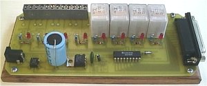
The 8-way Board with only 4 relays installed.
Parts List:
1 x PCB
8 x SPDT 12 volt Relays
1 x PCB mounted DB 25 Socket
1 x ULN2803 Integrated Circuit
1 x 1N4004 Diode
8 x 1N914 Diode
8 x 3mm Red LED
8 x 560 ohm 1/4 watt resistor
1 x 47uF Electrolytic Capacitor (up to 1000uF can be used depending on the power
supply)
1 x 0.01uF (approx) Green Cap
1 x LM7812 Voltage regulator (T220 case)
1 x 1 amp Bridge Rectifier
1 x 2.1mm Power Socket
25 pin Serial Cable - Male to Male
12 - 24 volt power supply with 2.1mm Plug
Optional: 8 x 3way PCB mounted terminal mounts.
Kit Assembly:
Begin with the smaller items such as the 1N914 doides and then the IC. You can then start on the 'taller' items like LEDs, resistors, regulator, bridge, green cap, etc. Once you have the basic components soldered in, carefully install the DB25 socket. Make sure that none of the pins get bent over as you're trying to wiggle everything into place. It's a nightmare to unsolder the socket if you make a mistake! Leave the relays until last.
Any 12 -15 volt 1 amp minimum AC or DC power supply can be used.
Download: Dos control software Windows control software
Search the net for third party software about 8 relay board.. it will work
![]() Also check the conversation about this project at the community. Post you
questions here.
Also check the conversation about this project at the community. Post you
questions here.
Title: The 8Way Relay Board
electronic circuit
Source: www.southwest.com.au
Published on: 2005-02-03
Reads: 1669
Print version: ![]()
Other electronic circuits and schematics from PC related
-
7 segment rolling display using PC
-
Simple Analog to Digital Converter
-
8 Channel software controlled fanbus with PWM
-
Simple PC thermometer
-
The Relay Sub Board
-
A Laboratory Control System for Cold Atom Experiments
-
Reading Data From The Parallel Port
-
Parallel Port Relay Interface
-
Opto-Isolated Stepper Motor Controller
-
PC Thermometer V2