Discharger for Receiver Battery Packs

You may have read about cycling NiCad batteries. If not, read a little here ( Red's R/C Battery Clinic) for an excellent overview. Overcharging apparently leads to voltage depression, which can be corrected by one or two complete discharges (to 1 to 1.1 volts per cell). On the other hand, over discharging the batteries to a low or zero voltage can damage them, and if the batteries have not been overcharged and have no voltage depression, cycling just uses up regular battery life. I designed and use this discharger occasionally to remove voltage depression and insure battery capacity is still ok for those planes that have no low voltage alarm.
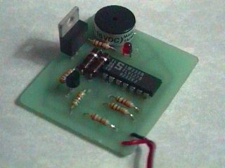
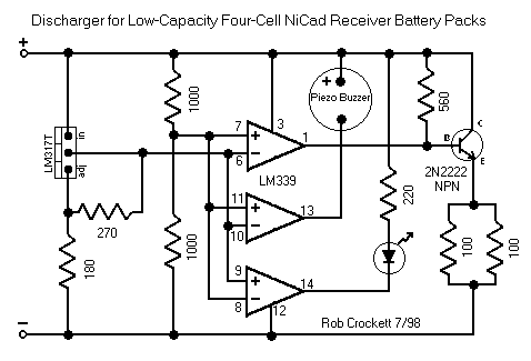
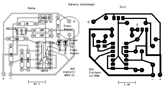
Note that the 100 ohm resistors are 1/2 watt (these are the load resistors), the rest are 1/4 watt. The red LED lights while discharging, buzzer sounds and discharge rate drops to 15-25mA (for the buzzer) when complete. The discharge load is 60mA to 110mA depending on the battery voltage. Since that's about the same current draw as my Hitec receiver and two HS-80's draw while flying handlaunch, I can use discharge time almost directly to indicate flying time. The buzzer uses enough current to keep a 150mA battery down, but when discharging a 600mA battery, the battery recovers quickly when the load is removed--the buzzer/discharger cycles on and off. Threshold voltage of the discharger is set to 4.2 volts. Since the discharger still draws some current when buzzing, try to disconnect the discharger once the alarm sounds--don't leave it going for hours lest the battery be over discharged.
There are a couple ways you could modify the circuit to work with a 5-cell 6-volt receiver battery pack. The two 1k resistors are a divider network, so one way would be to change the resistors to change the sampling voltage at the comparator. The formula for a divider network is Vout=Vin(R2/(R1+R2)) or R1=R2*((Vin/Vout)-1). Here, R1 is the resistor connected to the positive lead and pin 7 of the comparator, Vin is 5.25 volts (1.05 volts per cell discharge shutoff threshold), and Vout is the reference 2.1 volts (the voltage produced by the LM317T and the 180 and 270 ohm resistors). You can use R2 as the same 1k value that was there before. So R1=1000*((5.25/2.1)-1)=1500=1.5k. So swap the top 1k resistor in the schematic for a 1.5k, and the new shutoff voltage for your device will be 5.25 volts.
To increase the discharge rate, decrease the resistance of the load resistors. You could use four 100 ohm resistors in parallel instead of two, for example, and it would discharge twice as fast. Resistance of a number of resistors in parallel is the value of the resistor devided by the number of the resistors. Here, 100 ohms/ four resistors is 25 ohms. At five volts, current is (5 volts)/(25 ohms)=0.2 ampere or 200mA. Be careful not to decrease resistance too much however--the small signal transistor used in this particular circuit is probably only rated for maximum 500 mA.


Custom electronics:
I post this design not because I think this is a brilliant piece of circuit design but because the design works, and it can give you a start on your own experimentation. The idea is to use the power available from the discharging battery to monitor the voltage of the battery, shut off discharging at a preset voltage (here 1.05 volts/cell), and sound an alarm when discharging is complete. To do so means a voltage reference powered by the changing voltage of the battery, here the LM317T and the 180 with 270 ohm resistors. You could just as easily use a LM336 (see the low voltage warning buzzer page) or a zener with resistor, or something else as a reference. Since the reference voltage must be below the ambient battery voltage, a pair of 1k resistors provides the divided test voltage. The LM339 is a four way comparator.
This design uses really three comparators: in addition to the one driving the transistor, a comparator drives the LED and another drives the buzzer. But you could use a single comparator (like the LM311) with the buzzer across the emitter and collector of the transistor, and the LED in series with a 270 ohm resistor across (parallel with) the 100 ohm load resistors. With the transistor conducting, the voltage drop across base and emitter is low, and the buzzer is quiet. The tiny current in a piezo buzzer (7 mA), when the transistor is not conducting, would be divided between the load resistors and the LED, and the LED is dark.
A word about the comparator. The output of the comparator serves as a meager
source of current, but can sink current nicely. In other words, the high logic
output of the comparator will not drive the base of a NPN transistor as here.
The 560 ohm resistor provides the current here for the transistor base--the comparator
takes it away when its output drops to ground. Hmmm . . . . so, maybe use a PNP
transistor like a 2N3906 instead with emitter to + and collector to load, remove
the 560 resistor and connect the base through a 1k resistor to the output of the
comparator, then reverse the logic of the comparator by swapping the reference
with the test. . . hmmmmm. Could work. Yep . . . works.
Radio Shack parts:
| 273-074 | $2.99 | Miniature Piezo Buzzer, 12v, PC board mount |
| 271-312 | $7.99 | 1/4 watt 5% carbon film resistors, 500 pieces (Just do it!) |
| 276-1778 | $1.99 | LM317T adjustable voltage regulator |
| 276-1712 | $0.99 | Quad comparator LM339 |
| 276-1622 | $2.29 | LED assortment (20 count) |
| 276-2009 | $0.59 | NPN Silicon transistor MPS2222A (2N2222) |
Title: Discharger for Receiver Battery Packs
electronic circuit
Source: www.electronics-lab.com
Published on: 2005-02-02
Reads: 772
Print version: ![]()
Other electronic circuits and schematics from Models and model remote control
-
Receiver Battery Low Voltage Alarm
-
Deluxe Charge Rate Limiter for Small Capacity NiCad Batteries
-
Downed Model Locator II
-
Precision Receiver Battery Low Voltage Alarm
-
Remote control using VHF modules
-
Multi Rocket Launcher
-
Radio Remote Control using DTMF
-
Clap Activated Remote
-
Infrared Remote Control
-
Remote control using telephone
