Pulsing Third Brake Light

Caution: I'm checking into the legalities of this particular circuit at this time. Any type of flashing light on the main brake lights is prohibited and illegal in most states of the U.S.A. I'm verifying for the same here in Canada. In the mean time, use this circuit at your own risk and be aware that the possibility exists to be stopped by law enforcement if you implement this circuit in your vehicle.
Parts List
Semiconductors:
IC1,IC2 = 555 Timer, RS #276-1723
SCR1 = NTE/ECG5402, RS #276-1067, EC103A, MCR104, etc.
Q1 = NTE/ECG197, SK3083, TIP125, or equivalent
D1,D2,D3 = 1N4148, 1N914, NTE/ECG519, RS #276-1122
D4,D5 = 1N5400, NTE/ECG5850, RS #276-1141, or equivalent
Resistors:
R1 = 18K
R2 = 330 ohm (RS #271-1315)
R3 = 270K
R4 = 82K
R5,R6 = 1K2
R8 = 100 ohm (RS# 271-1311)
P1 = 50K, 10-turn
P2 = 10K, 10-turn
Capacitors:
C1 = 100ВµF/16V (RS# 272-1016)
C2 = 22ВµF/16V (RS# 272-1014)
C3 = 220ВµF/16V (RS# 272-1017)
C4 = 10ВµF/16V (RS# 272-1013)
Q1 is a PNP Silicon Audio Power Out/Medium Power Switch Transistor, 7A, with a TO-220 case. As long as you have a transistor which is close it will work fine. The SCR is a 100vrm, 0.8A, sensitive gate with a TO-92 case. Diodes D1, D2 and D3 are standard small signal diodes. Power diodes D4 and D5 are the 6A, 50prv types, cathode case. The 60vrm type will work as well. I used for IC1 & IC2 the LM555 type. P1 controls the 'on' and pulse-duration, P2 controls the pulse-timing.
Applying the Brakes: When you first press the brakes, this circuit will turn on your 3rd brake light via the main brake lights. After about a second a series of short strobe pulses occur. The number of pulses range from approximately 1 to 10, depending on the setting of P1/P2 and when the brake pedal was applied last. After the pulses have been applied the third brake light assumes normal operation. The prototype was set for five flashes which seemed more than enough. Two days later I re-adjusted the trimmer potentiometers for 4 flashes--1/2 second pause--4 flashes. Looks pretty cool!
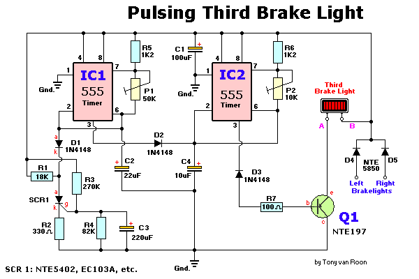
Circuit Description: The schematic consists of two 555 timer/oscillators in a dual timer configuration both setup in astable mode. When power is applied via the brake pedal, the brake light driver Q1 is switched on via the low-output pin 3 of IC2, and timer IC1 begins its timing cycle. With the output on pin 3 going high, inhibiting IC2's pin 2 (trigger) via D2, charge current begins to move through R3, R4 and C2.
When IC1's output goes low, the inhibiting bias on pin 2 of IC2 is removed and IC2 begins to oscillate, pulsing the third brake light via the emitter of Q1, at the rate determined by P2, R6, and C4. That oscillation continues until the gate-threshold voltage of SCR1 is reached, causing it to fire and pull IC1's trigger (pin 2) low. With its trigger low, IC1's ouput is forced high, disabling IC2's trigger. With triggering disabled, IC2's output switches to a low state, which makes Q1 conduct turning on the 3rd Brake Light until the brakes are released. Obviously, removing the power from the circuit at any time will reset the Silicon Controlled Rectifier SCR1, but the RC network consisting of R4 and C2 will not discharge immediately and will trigger SCR1 earlier. So, frequent brake use means fewer flashes or no flashes at all. But I think that's okay. You already have the attention from the driver behind you when you used your brakes seconds before that.
The collector/emitter voltage drop accross Q1 together with the loss over the series fed diodes D4/D5, will reduce the maximum available light output, but if your car's electrical system is functioning normally in the 13 - 14volt range, these losses are not noticeable.
Building Tips: You can easily build this circuit on perfboard or on one of RS/Tandy's experimentors boards (#276-150), or use the associated printed circuit board listed here.
Keep in mind that Q1 will draw most likely 2 or 3 amps and mounting this device on a heat sink is highly recommended. Verify that the scr is the 'sensitive gate' type. In incandecent bulbs, there is a time lag between the introduction of current and peak brightness. The lag is quite noticeable in an automotive bulb, so the duration of a squarewave driving such a bulb should be set long enough to permit full illumination. For that reason, and because lamps and car electrical systems vary, adjustment via P1 and P2 is necessary to provide the most effective pulse timing for your particular vehicle.
The reason that the third light is connected to both brake lights is to eliminate the possibility of a very confusing display when you use your turn signal with the brakes applied.
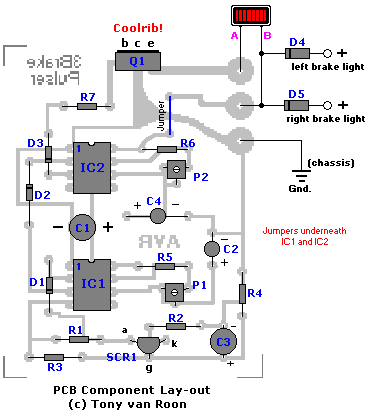
The cathode of D4 and D5 are tied together and go to point 'B' of the third brake light in the component layout diagram. Point 'A' goes to the other leg of the third brake light. Most if not all third brake lights in Canada & USA have two wires, the metal ones also have a ground wire which obviously goes to ground. I don't know the wiring schema for Australian and European third brake lights.
Don't forget the three jumpers on the pcb; two jumpers underneath IC1/IC2 between pin 4/8 and the one near Q1/R6.
If you use a metal case, don't forget to insulate the D4/D5 diodes.
Some 90's cars, like my 1992 Mercury Sable, have two bulbs inside the third brake light, each bulb is hooked up seperately to the left and right brake light for reasons only Ford knows. Click here for a possible 2-bulb hookup. It shows how I modified mine to get it working; and that was easier than I expected. Current draw with the two bulbs was measured at 1.85Amps (1850mA). Even with double the current none of the circuit components were getting hot. I had to re-adjust the two pots to make it flash since the bench testing was done with one bulb.
Bench Testing:I tested different semiconductors like the 1N5401/1N5404, NTE153, and 4A type powerdiodes for D4/D5. All worked very well. As expected, Q1 is getting very hot. Current draw was measured between 680 - 735mA with a regular automotive 'headlight' bulb, extra heavy duty to make sure the circuit was safe. I tested several other power transistors including some darlingtons like the TIP125 and the TIP147. I eventually settled for the TIP125 myself because I had it available but any thing with 5A or more will do fine.
The actual third brake bulb is a lot smaller. Adjusting the trimpots (P1/P2) may take a bit of patience but really fine-tunes the circuit well. The only drawback of this circuit is the discharge lag coming from the electrolytic capacitor C2 and the R4 resistor. Especially if the brakes are used often or at short intervals the third brake light will not flash or maybe flash once or twice. Again, this is because the R-C combo does not have enough time to discharge in between braking. It takes about 12 seconds to discharge C2.
 |
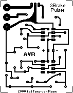
The pcb measures 2 x 2.5 inch (5 x 6.4cm or 170 x 200 pixels) at 2 colors and is shown smaller when you print these pages. If you need a direct, full size copy of the pcb I suggest to load the gif file into a program like Paint Shop Pro or one of the many gif viewers available. |
 |
The layout is enlarged a bit for a better component view.
Note that Q1 is drawn soldered on the pcb but if you have a metal case
you can put it anywhere on the metal case (as a coolrib) and use havy duty
wiring between Q1 and the PCB. CORRECTION: SCR1's anode/kathode were shown reversed (fixed: 2-26-2000).
Copyright В© 2000 - Tony van Roon |
Title: Pulsing Third Brake Light
electronic circuit
Source: www.electronics-lab.com
Published on: 2005-02-02
Reads: 1369
Print version: ![]()
Other electronic circuits and schematics from Automotive
-
Synchronized multi-spark module (SMSM) for Electronic Ignition Devices (EID)
-
Capacitor Discharge Ignition Circuit (CDI)
-
Dome light dimmer for Cars
-
Car Battery Charger
-
Lighting Third Brake Light
-
Ultrasonic Parking Sonar
-
Wiper Speed Control
-
Headlights Timer
-
Speed-limit Alert
-
Charge Monitor for 12V lead acid battery
