Building on blocs
The first circuit is shown in Figure 9.5, and from this you will see two 9 V batteries are used as a power supply. This is because the 741 needs what’s called a three-rail power supply i.e., one with a positive rail, a negative rail, and a ground rail 0 V. Now you may ask how two batteries can be used to provide this. Well the answer’s simple, join them in series. This gives a +18 V supply, a 0 V supply, and at the mid-point between the batteries, a +9 V supply. As voltages are only relative anyway, we can now consider the +9V supply to be the middle ground rail of our three-rail power supply and refer to it as 0 V. The +18 V supply then becomes the positive rail (+9 V) and the 0 V supply becomes the negative rail (–9 V).
Hint:
The 741 is commonly referred to as an operational amplifier — shortened to op-amp. The term comes from the earlier days in electronics when discrete components were built into circuits and used as complete general-purpose units. An op-amp, as its name suggests, is a general-purpose amplifier which is more-or-less ready-to-use. Years ago it might have been a large metal box full of valves and wiring. Later it would have been a circuit board on which the circuit was built with transistors. But nowadays nobody uses op-amps made with discrete components, because modern technology has produced IC op-amps such as the 741. Given the choice, would you use discrete components to build an op-amp of the complexity of that in Figure 9.1, or would you use a 741?
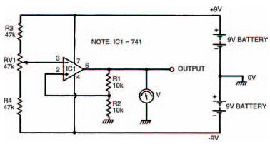
Figure 9.5 Our first experimental circuit: a non-inverting amplifier with a threerail power supply
Besides the ease of use inherent with ICs, they are also cheaper than discrete counterparts — the 741 is priced at around 40 pence. Building the circuit using transistors would cost many times this.
As the 741 is an operational amplifier, it makes sense that the first circuit we look at is an amplifying circuit. But what sort of amplifier does it form? Well the easiest way to find out is to build the circuit, following the breadboard layout of Figure 9.6, and then use your multi-meter to measure the voltage at the circuit’s input (pin 3) and compare it with the voltage at the circuit’s output (pin 6). The voltages should be measured for a range of values, adjusted by the preset variable resistor RVl, and should be written into Table 9.1 as you measure them.
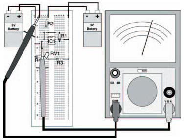
Figure 9.6 The breadboard layout for the circuit in Figure 9.5. Note that in this diagram the input voltage is being measured
Table 9.1 To show the results of your measurements
Note that in Table 9.1 there are measurement points at negative as well as positive voltages: the best way of taking the readings is to first take the positive readings then turn the meter round i.e., swap the meter leads over so that the black lead measures the voltage at pin 6 and the red lead connects to 0 V, to measure the negative readings.
The results which were taken in my circuit are given in Table 9.2, and your results should be something like this, although differences may occur. From these results you should see that the circuit amplifies whatever voltage is present at the input by about two, so that the output voltage is about twice that of the input. This is true whatever the input voltage. Don’t worry if your results aren’t that close to the ideal ones, it’s only an experiment.
Table 9.2 The results of my measurements
This particular circuit is a fairly basic amplifier which simply amplifies the input voltage. For one reason or another, which you’ll appreciate soon, it’s called a non-inverting amplifier. Its gain is given by the expression:

and if you insert the values of resistors R1 and R2 into this expression you will see why the circuit gives an experimental gain of about two.
As the circuit has a gain which is dependent on the values of resistors R1 and R2, it is a simple matter to adjust the circuit’s gain, by changing one or both resistors. Try changing resistor R1 to say 22 k and see what the gain is (it should be about three).
Take note
Theoretically, of course, the circuit could have any gain we desire, just by inserting the right values of resistances. But in practice there are limits. If, say, the circuit’s gain was set to be 20, and an input voltage of 1 V was applied, the circuit would attempt to produce an output voltage of 20 V. But that’s not possible — the output voltage can’t be greater than the power supply voltage (fairly obvious), which in this case is ±9 V. The answer, you may think, is to wind up the power supply voltage to + and –20 V, and, yes, you can do this to a certain extent, but again there are practical limitations. The 741, for example, allows a maximum power supply voltage of about ±15 V, above which it may be damaged.
<< Integrated circuits