Practically there
Figure 7.16 shows a circuit we’ve already seen and built before: a 555-based astable multi-vibrator. We’re going to use it to demonstrate the actions of some of the principles we’ve seen so far. Although the output of the astable multi-vibrator is a squarewave, we’re going to imagine that it is a sinewave such as that from a 230 V a.c. mains powered transformer. Figure 7.17(a) shows the squarewave output, and if you stretch your imagination a bit (careful, now!), rounding off the tops and bottoms of the waveform, you can approximate it to an alternating sinewave.
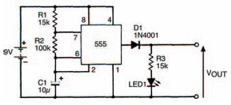
Figure 7.16 An astable multi-vibrator circuit. This can be used to demonstrate some of the principles under discussion
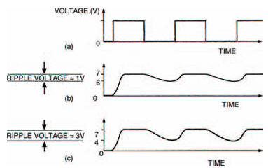
Figure 7.17(a) The squarewave output from the circuit in Figure 7.16 experimentally modified by a 100 kΩ resistor (b) and a 10 kΩ resistor (c)
Build the circuit, as shown in the breadboard layout of Figure 7.18, and measure the output voltage. It should switch between 0 V and about 8 V.
Now let’s add a smoothing capacitor Cs and load resistor RL to the output of our imaginary rectified power supply, as in Figure 7.19. The output voltage of the smoothing stage is now fairly steady at about 6V5 indicating that smoothing has occurred. Although you can’t see it, the voltage waveform would look something like that in Figure 7.17(b), with a ripple voltage of about 1 V. The breadboard layout for the circuit is shown in Figure 7.20.
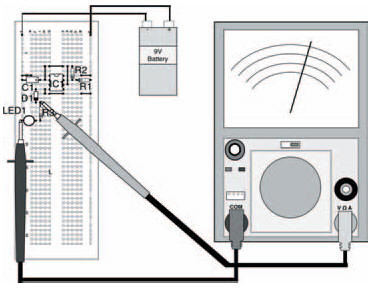
Figure 7.18 The breadboard layout of the circuit in Figure 7.16
We can show what happens when load current increases by putting a lower value load resistor in circuit — take out the 100 kΩ resistor and put a 10 kΩ resistor in its place. The ripple voltage now increases causing greater changes in the d.c. output level, and the whole waveform is shown as Figure 7.17(c).
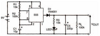
Figure 7.19 The same circuit with a smoothing capacitor added
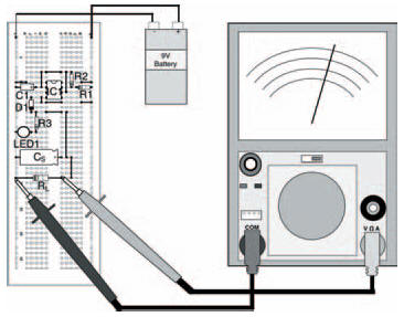
Figure 7.20 The breadboard layout for the circuit in Figure 7.19
That’s all for this chapter. Next chapter we’ll move onto another semiconductor — possibly the most important semiconductor ever — the transistor. Try the quiz over the page to see what you’ve learned here.
<< Stability built in