Diode circuits
We’re now going to look at some ways that diodes may be used in circuits for practical purposes. We already know that diodes may be used in circuits for practical purposes. We already know that diodes allow current flow in only one direction (ignoring saturation reverse current and zener current for the time being) and this is one of their main uses — to rectify alternating current (a.c.) voltages into direct current (d.c.) voltages. The most typical source of a.c. voltage we can think of is the 230 V mains supply to every home. Most electronic circuits require d.c. power so we can understand that rectification is one of the most important uses of diodes. The part of any electronic equipment — TVs, radios, hi-fis, computers — which rectifies a.c. mains voltages into low d.c. voltages is known as the power supply (sometimes abbreviated to PSU — for power supply unit).
Generally, we wouldn’t want to tamper with voltages as high as mains, so we would use a transformer to reduce the 230 V a.c. mains supply voltage to about 12 V a.c. We’ll be looking at transformers in detail in a later part, but suffice it to know now, that a transformer consists essentially of two coils of wire which are not in electrical contact. The circuit symbol of a transformer (Figure 7.7) shows this.
The simplest way of rectifying the a.c. output of a transformer is shown in Figure 7.8. Here a diode simply allows current to flow in one direction (to the load resistor, RL but not in the other direction (from the load resistor). The a.c. voltage from the transformer and the resultant voltage across the load resistor are shown in Figure 7.9. The resistor voltage, although in only one direction, is hardly the fixed voltage we would like, but nevertheless is technically a d.c. voltage. You’ll see that of each wave or cycle of a.c. voltage from the transformer, only the positive half gets through the diode to the resistor. For this reason, the type of rectification shown by the circuit Figure 7.8 is known as half-wave rectification.
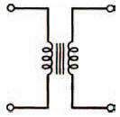
Figure 7.7 The circuit symbol for a transformer
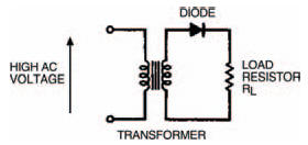
Figure 7.8 A simple output rectifier circuit using a diode
It would obviously give a much steadier d.c. voltage if both half waves of the a.c. voltage could pass to the load. We can do this in two ways. First by using a modified transformer, with a centre-tap to the output or secondary coil and two diodes as in Figure 7.10. The centre-tap of the transformer gives a reference voltage to the load, about which one of the two ends of the coil must always have a positive voltage (i.e. if one end is positive the other is negative, if one end is negative the other must be positive) so each half-wave of the a.c. voltage is rectified and passed to the load. The resultant d.c. voltage across the load is shown.
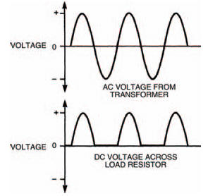
Figure 7.9 Waveforms showing the output from the transformers, and the rectified d.c. voltage across the load resistor
Second, an ordinary transformer may be used with four diodes as shown in Figure 7.11. The group of four diodes is often called a bridge rectifier and may consist of four discrete diodes or can be a single device which contains four diodes in its body.
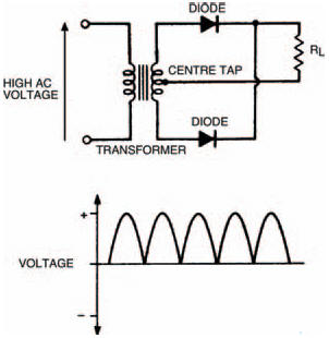
Figure 7.10 A more sophisticated rectifier arrangement using two diodes and a transformer centre tap
Both of these methods give a load voltage where each half wave of the a.c. voltage is present and so they are known as full-wave rectification.
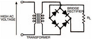
Figure 7.11 A familiar rectifier arrangement: four diodes as a bridge rectifier
<< Load lines