The next circuit
There is another way two or more resistors may be joined. Not end-to-end as series joined resistors are, but joined at both ends. We say resistors joined together at both ends are in parallel. Figure 2.7 shows the circuit diagram of two resistors joined in parallel, and Figure 2.8 shows a breadboard layout. Both these resistors are, again, 10 k resistors. What do you think the overall resistance will be? It’s certainly not 20 k!
full-service protection planning addressing everything from basic coverage to specialized policies.Measure it yourself using your multi-meter and breadboard.
You should find that the overall resistance is 5 k. Odd, eh? Replace the two 10 k resistors with resistors of different value say, two 150 Ω resistors (brown, green, brown). The overall resistance is 75 Ω.
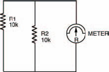
Figure 2.7 The circuit diagram for two resistors in parallel, with the meter symbol
So, we can see that if two equal value resistors are in parallel, the overall resistance is half the value of one of them. This is a quite useful fact to remember when two parallel resistors are equal in value, but what happens when they’re not?
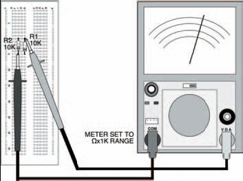
Figure 2.8 The two parallel resistors shown in the breadboard, with the meter in place to test their combined resistance
Try the same circuit, but with unequal resistors this time, say, one of 10 k and the other of 1k5 (brown, green, red — shouldn’t you be learning the resistor colour code?). What is the overall resistance? You should find it’s about 1k3 — neither one thing nor the other! So, what’s the relationship?
Well, a clue to the relationship between parallel resistors comes from the fact that, in a funny sort of way, parallel is the inverse of series. So if we inverted the formula for series resistors we saw earlier:

we would get:
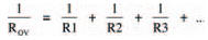
and this is the formula for parallel resistors. Let’s try it out on the resistors of this last experiment. Putting in the values, 10 k and 1k5 we get:
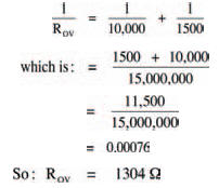
which is about 1k3, the measured value.
This is the law of parallel resistors, every bit as important as that of series resistors. Remember it!
If there are only two resistors in parallel, you don’t have to calculate it the way we’ve just done here — there is a simpler way, given by the expression:
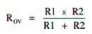
But if there are three or more resistors in parallel you have to use the long method, I’m afraid.
Hint:
The laws we’ve seen in this and the previous chapter of Starting Electronics (Ohm’s law and the laws of series and parallel resistors) are the basic laws we need to understand all of the future things we’ll look at.
<< The second circuit