IR Remote Control Tester
Notes:
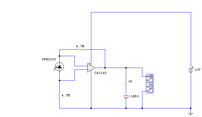
I have used a photodiode, SFH2030 as an infra red sensor. A MOSFET opamp, CA3140
is used in the differential mode to amplify the pulses of current from the
photodiode. LED1 is an ordinary coloured led which will light when IR radiation
is being received. The output of the opamp, pin 6 may be connected to a
multimeter set to read DC volts. Infra red remote control strengths can be
compared by the meter reading, the higher the reading, the stronger the infra
red light. I aimed different remote control at the sensor from about 1 meter
away when comparing results. For every microamp of current through the
photodiode, about 1 volt is produced at the output. A 741 or LF351 will not work
in this circuit. Although I have used a 12 volt power supply, a 9 volt battery
will also work here.
Title: IR Remote Control Tester
electronic circuit
Source: www.electronics-lab.com/
Published on: 2005-02-10
Reads: 974
Print version: ![]()
Other electronic circuits and schematics from Test and measurement
-
A simple Remote control Tester
-
Digital Voltmeter
-
Contactless Mains Voltage Indicator
-
Latching Continuity Tester
-
Thermostat for 1KW Space Heater (SCR controlled)
-
Frequency Comparator
-
Triangle / Squarewave Generator
-
Mosfet TESTER
-
XTal Tester
-
Continuity Tester