Frequency Comparator
This circuit uses a 74HCT74, 74HCT00, and a LM311 to form a frequency comparator. The two pulse trains are fed to two D-type flip-flops (triggered by the leading edges). The flip-flops' outputs are compared in a NAND gate. If the output of the NAND gate becomes "0", the flip-flops are reset. If the frequency of F1 is higher than the frequency of F2, the signal "Q2" consists of needles and "Q1" is a pulse train.
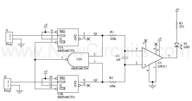
Therefore, the energy content of Q1 is higher than that of Q2. Q1 and Q2 come via a low-pass filter (consisting of R1, R2 and C1) and are compared by an analog comparator circuit (IC3). The comparator drives an LED and can act as a digital output. For the case when the frequency of F1 is lower that the frequency for F2, the signal Q1 consist of needles and Q2 is a pulse train.
Title: Frequency Comparator
electronic circuit
Source: unknown
Published on: 2005-08-27
Reads: 1338
Print version: ![]()
Other electronic circuits and schematics from Test and measurement
-
Voltage follower with 1G ohm input resistance
-
Capacitance Meter
-
Digital Voltmeter
-
AC Line Current Detector
-
Electronic Thermostat and Relay Circuit
-
XTal Tester
-
Zener Diode Tester
-
Picoammeter circuit with 4 ranges
-
Inductive meter adapter
-
Led display digital Voltmeter