Mini-box 2W Amplifier
| -- Designed for self-powered 8, 4 & 2 Ohm loudspeakers |
| -- Bass-boost switch |
Circuit diagram:
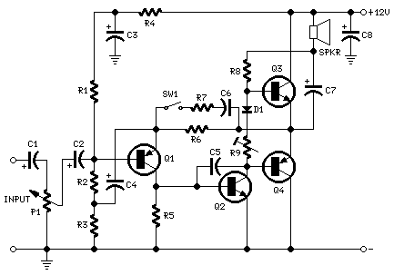
Parts:
|
P1 = 10K |
Log.Potentiometer |
|
R1,R2 = 33K |
1/4W Resistors |
|
R3 = 33R |
1/4W Resistor |
|
R4 = 15K |
1/4W Resistor |
|
R5,R6 = 1K |
1/4W Resistors |
|
R7 = 680R |
1/4W Resistor |
|
R8 = 120R |
1/2W Resistor |
|
R9 = 100R |
1/2W Trimmer Cermet |
|
|
|
|
C1,C2 = 10ВµF |
63V Electrolytic Capacitors |
|
C3 = 100ВµF |
25V Electrolytic Capacitor |
|
C4,C7 = 470ВµF |
25V Electrolytic Capacitors |
|
C5 = 47pF |
63V Ceramic Capacitor |
|
C6 = 220nF |
63V Polyester Capacitor |
|
C8 = 1000ВµF |
25V Electrolytic Capacitor |
|
|
|
|
D1 = 1N4148 |
75V 150mA Diode |
|
|
|
|
Q1 = BC560C |
45V 100mA PNP Low noise High gain Transistor |
|
Q2 = BC337 |
45V 800mA NPN Transistor |
|
Q3 = TIP31A |
60V 4A NPN Transistor |
|
Q4 = TIP32A |
60V 4A PNP Transistor |
|
|
|
|
SW1 |
SPST switch |
|
|
|
|
SPKR |
3-5 Watt Loudspeaker, 8, 4 or 2 Ohm impedance |
Device purpose:
This amplifier was designed to be self-contained in a small loudspeaker box. It can be feed by Walkman, Mini-Disc and CD players, computers and similar devices having line or headphone output. Of course, in most cases you'll have to make two boxes to obtain stereo.
The circuit was deliberately designed using no ICs and in a rather old-fashioned manner in order to obtain good harmonic distortion behaviour and to avoid hard to find components. The amplifier(s) can be conveniently supplied by a 12V wall plug-in transformer. Closing SW1 a bass-boost is provided but, at the same time, volume control must be increased to compensate for power loss at higher frequencies.
In use, R9 should be carefully adjusted to provide minimal audible signal cross-over distortion consistent with minimal measured quiescent current consumption; a good compromise is to set the quiescent current at about 10-15 mA.
To measure this current, wire a DC current meter temporarily in series with the collector of Q3.
Technical data:
Output power: 1.5 Watt RMS @ 8 Ohm, 2.5 Watt @ 4 Ohm, 3.5 Watt @ 2 Ohm (1KHz
sinewave)
Sensitivity: 100mV input for 1.5W output @ 8 Ohm
Frequency response: 30Hz to 20KHz -1dB
Total harmonic distortion @ 1KHz & 10KHz: Below 0.2% @ 8 Ohm 1W, below 0.3% @ 4
Ohm 2W, below 0.5% @ 2 Ohm 2W.
Title: Mini-box 2W Amplifier
electronic circuit
Source: www.redcircuits.com
Published on: 2005-02-01
Reads: 1715
Print version: ![]()
Other electronic circuits and schematics from Audio
-
1.5W Audio power amplifier (12V)
-
Headphone Amplifier
-
Minimalist Discrete Hi-Fi Preamp
-
22W Stereo Amplifier
-
Classic Audio Mixer
-
Amplifier 2x30W with STK465
-
Digital Volume Control
-
Stereo Channel Selector
-
Electronics Attenuator
-
Infrared Head Phones