Minimalist Discrete Hi-Fi Preamp
Introduction
Note that the project described here has been superceeded by the new Revision A version. The new circuit uses a dual supply, and does not include the power supply. P05 is ideally suited for this new version.
A preamp designed for the minimalist, and having no frills at all is the design goal for this project. It is designed as a preamp for the Death of Zen (DoZ) Class-A power amp (Project 36), and has very low levels of noise and distortion, in a minimum component count, fully discrete circuit.
This gain module can be used as the basis for any preamp - performance is exemplary, with low noise, wide bandwidth, and it sounds extremely good indeed.
You can add as many inputs as you need, and the only controls are volume and input selection. A power switch is also a good idea, but if you wanted to you could leave the preamp running all the time. This is not necessary, as it will reach a stable operating condition within a few seconds, and will not change its characteristics to any audible degree. An advantage of a power switch is that a +30V signal can be used to switch the power on the power amplifiers, so only a single switch is needed for the system. This can be expanded to switch power to the entire music centre, including CD player(s), tuner, etc.
The preamp can also be used with other amplifiers, and can drive an impedance of 2k Ohms with ease. Although shown using a single supply (to easily match the DoZ power amp), it can also be operated with a dual +/- 15V supply if desired, although this is not really recommended (and is not a trivial undertaking, either) partly because of the possibility of reverse biasing the output capacitors (which cannot be omitted), and partly because of other modifications that are needed for it to work properly.
As shown, frequency response is absolutely flat from 10Hz to 100kHz, without any frequency stabilisation required. The table below shows the rated performance of the gain module.
| Distortion | < 0.01% |
| Output Voltage | 6.0 V RMS |
| Output Impedance | < 100 Ohms |
| Minimum Load | 2k Ohms |
| Frequency Response | 10Hz - 100kHz (-0.5dB) |
| Voltage Gain | 10dB nominal |
| Supply Voltage | 30V |
| Supply Current | <10m |
Description
The circuit for the amplifier module is shown in Figure 1, and as can be seen is very simple. Two of these can easily be built on a piece of Veroboard, although the PCB makes it a lot easier. This preamp relies on a completely hum free power supply, as it is not an opamp, and cannot reject supply noise as well. This is not to say that the power supply rejection is especially bad, just that it is not as good as an opamp. The power supply is shown below, and this will have a ripple and noise of less than 10uV if built as specified.
Figure 1 - Gain Module
D1 and D2 are 1N4148 (or 1N914), and together with Q2 form a current source providing a bias current of about 7mA. This stage is not an amplifier, but an active (and very linear) load, allowing the amplifying transistor Q3 to provide a high gain with excellent linearity. Feedback is applied through R5, with R4 setting the AC feedback ratio and thus the voltage gain of the amp. The transistors Q2 and Q3 operate at about 100mW and will get slightly warm in operation.
The trimpot VR1 is used to set the voltage at the collectors of Q2 and Q3 to 1/2 the supply voltage (15V), and a single unit can be used for a stereo pair with no interaction or other undesirable side effects. A 100k resistor is then used to supply bias for each preamp module. If you really don't want to use the pot, you can use a 10k resistor from the +ve of C2 to earth, and a 22k resistor to the supply. This will not allow you to set the quiescent voltage as accurately, but will be acceptable for normal use. R8 ensures that the output capacitor is properly charged with no output connected, and can be left out if the output is connected directly to the volume control as shown below.
The distortion of the preamp is reasonably consistent with frequency, and is less than 0.01%. I measured about 0.0075% - this is just above the residual of my signal generator (0.006%), so it is presumably much better than this, but I can't measure it. A rough guess would be the difference between the two, giving 0.0015%, but I prefer to err on the side of caution.
Frequency response is flat to within -0.2dB from 10Hz to 100kHz, and even at 100kHz, square wave performance is almost perfect, showing slight rounding and no ringing or instability of any kind. Measured output impedance is 84 Ohms, and the circuit can drive 6 Volts RMS into a 2.2k Ohm load easily. These are excellent figures, considering the simplicity of the circuit. The gain is nominally 3.2 (10dB) as shown, and is easily changed by varying R4 - increase the value to decrease gain and vice versa.
The preamp modules provide the only gain stage, and may be bypassed for high level signals (such as CD players) that have enough signal to drive the power amp directly. This is a great advantage for those who want the minimum number of components in line with the signal. The circuit cannot be direct coupled, however, since it operates on a single supply. This means that polyester caps can be used at the inputs, but for low impedance outputs, electrolytic capacitors must be used. These may be bypassed with 100nF polyester caps, but the frequency response is not altered to any significant degree (not measurable at 100kHz), and there is no measurable decrease in distortion with the bypass caps.
Figure 2 - Preamp Wiring Suggestion
Figure 2 shows one channel of a suggested wiring for the preamp. This is duplicated exactly for the other channel, and the switch and volume control are common to both. The CD input bypasses all electronics and is applied directly to the volume control, and the low level inputs use the gain of the modules to bring their level up to that of the CD player. This introduces a bit more switching, but many audiophiles will prefer this method. Note that when switched to CD, the input of the preamp is earthed to prevent any noise pick-up.
The switching requires a 4-pole, 5 position rotary switch for both channels, and a dual-gang pot. I strongly suggest that a linear pot is used, with the resistor as shown. Although this produces a variable impedance to the source, it is a better approximation of a log pot than those you can buy at normal outlets, and has much better tracking between channels. If you can get a conductive plastic logarithmic pot, do not use the resistor, as these are generally much better than the normal carbon film types, and the resistor will ruin the log curve.
In some cases - due to an amplifier with unusually low input sensitivity for instance - an output gain stage might be needed. This would typically use another gain module using the circuit above, but generally with lower gain. It is expected that a gain of 2 (6dB) will be enough for any amplifier, since this will provide an output of 4V RMS for a CD players typical 2V output. I have found that with typical sources, a preamp gain of about 10dB is sufficient to drive a typical power amplifier, so the additional gain will probably not be needed.
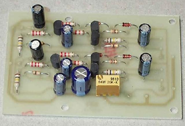
Photo of Prototype
The photo shows what the final unit looks like. Since this was taken of the prototype board, the silk screen component overlay is not present, and I used "ordinary" resistors for all my initial tests. Better noise performance will result from using metal film resistors.
Power Supply
The power supply must be free from hum and noise, and the circuit shown in Figure 3 should be used. Do not use 3 terminal regulators, as the applied voltage is too high, and they will fail. A discrete circuit is (usually) not quite as good, but is simple to build and reliable. The shunt regulator shown here will be hard to beat with any circuit though, mainly because of the filtering used, although the regulator does dispose of a lot of hum by itself.
Figure 3 - Power Supply Circuit
This circuit is suitable for two gain modules as shown. If you want to use more, then R1 and R2 will have to be reduced in value. With a 40V input and a total of 200 Ohms, maximum current is 50mA for 30V output. I would suggest that a minimum of 20mA flows in the shunt regulator, so if you wanted to run 4 gain modules, reduce the value of R1 and R2 to about 82 Ohms. You can expect a very small increase in noise, but this will not be audible. The Zener diode must be a 30V device, and should be rated at 1 Watt. Your local electronics supplier will be able to tell you what type number you need. All electrolytic capacitors should be rated at 63V. If you cannot get a 16V transformer, you could use a unit with up to 20V AC output, but you will have to re-calculate the value of R1 and R2.
You can add decoupling between channels to prevent any possibility of crosstalk, but even without this it should be possible to obtain excellent channel separation, since the circuit operates in Class-A and does not vary the supply current with signal (as do opamps and many other circuits). The power transformer does not have to be high power - 20VA is more than enough due to the low current drain (about 50mA).
Because this is a shunt regulator, it has "automatic" protection against short circuits at the output. You should not test this though, because the discharge from the output capacitor will cause a very high peak current, and may damage the cap. Why the shunt regulator? Because in the interests of greatest simplicity, this is the ultimate. Since there is a resistor / capacitor "pi" filter, hum and noise are very low, and should be less than 10uV RMS under normal operation. The shunt regulator also acts to reduce hum, since this is "seen" by the circuit as a varying voltage, and the shunt circuit will try to compensate by modulating its shunt impedance to minimise the fluctuating voltage.
The series 100 Ohm resistors (R1 & R2) carry the preamp + shunt current, which will typically be around 50mA, so dissipation is quite low. 5W resistors should be used to ensure reliability, especially in the event of an accidental short circuit on the output. In this event, dissipation will be about 7 to 8W, so the resistors will get very hot. The BD139 shunt transistor will operate at about 50mA when the supply is not loaded by the preamp modules, and will dissipate about 1.5 Watts. This must be mounted on a suitable heatsink, having a thermal resistance of no more than 10°C / Watt. This will keep the transistor nice and cool under worst case conditions, with a typical maximum temperature rise of 15°C.
As always, be very careful with the mains wiring. If possible, use a 16V AC power pack and mount it remotely from the preamp so that there is no possibility of inducing hum into the circuit from the transformer. Using the full wave voltage doubler as shown will provide about 40V minimum before regulation. This is more than enough to ensure that the preamp supply remains stable.
Title: Minimalist Discrete Hi-Fi Preamp
electronic circuit
Source: unknown
Published on: 2012-09-20
Reads: 936
Print version: ![]()
Other electronic circuits and schematics from Audio
-
Balanced Low Noise Microphone Preamp
-
18W Audio Amplifier
-
22W Stereo Amplifier
-
5 band graphic equalizer using a single IC/chip
-
Precision Audio Millivoltmeter
-
Electret Microphone Pre-Amplifier
-
Headphone Monitoring Switch
-
Sound Pressure Level Meter
-
Guitar Amplifier
-
Phono Preamplifier