Headphone Amplifier
High Quality unit
No need for a preamplifier
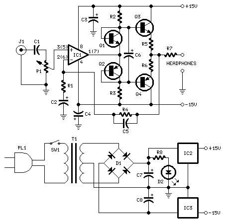
Amplifier parts:
P1_____________22K Log.Potentiometer (Dual-gang for stereo)
R1____________560R 1/4W Resistor
R2,R3__________10K 1/4W Resistors
R4_____________12K 1/4W Resistor
R5,R6___________2R2 1/4W Resistor
R7_____________22R 1/2W Resistor
C1______________1ВµF 63V Polyester Capacitor
C2,C3,C4______100ВµF 25V Electrolytic Capacitors
C5_____________22pF 63V Polystyrene or Ceramic Capacitor
C6_____________22ВµF 25V Electrolytic Capacitor
IC1___________LM833 or NE5532 Low noise Dual Op-amp
Q1,Q3_________BC337 45V 800mA NPN Transistors
Q2,Q4_________BC327 45V 800mA PNP Transistors
J1______________RCA audio input socket
Power supply parts:
R7______________2K2 1/4W Resistor
C7,C8________2200ВµF 25V Electrolytic Capacitors
D1____________100V 1A Diode bridge
D2____________5mm. or 3mm. Red LED
IC2___________7815 15V 1A Positive voltage regulator IC
IC3___________7915 15V 1A Negative voltage regulator IC
T1____________220V Primary, 15 + 15V Secondary 5VA Mains transformer
PL1___________Male Mains plug
SW1___________SPST Mains switch
Notes:
- Can be directly connected to CD players, tuners and tape recorders.
- Tested with several headphone models of different impedance: 32, 100, 245, 300, 600 & 2000 Ohms.
- Can drive old 8 Ohms impedance headphones, but these obsolete devices are not recommended.
- Schematic shows left channel and power supply.
- Numbers in parentheses show IC1 right channel pin connections.
- A correct grounding is very important to eliminate hum and ground loops. Connect in the same point the ground sides of J1, P1, C2, C3 & C4. Then connect separately the input and output grounds at the power supply ground.
Technical data:
Output voltage: Well above 5V RMS on all loads
Sensitivity: 250mV input for 5V RMS output
Frequency response: Flat from 30Hz to 20KHz
Total harmonic distortion @ 1KHz & 10KHz: Below 0.005% on 32 Ohms load and up to
4V RMS output (typical 0.003%)
Total harmonic distortion @ 1KHz & 10KHz: Below 0.005% on 100 to 2000 Ohms load
and up to 5V RMS output (typical 0.003%)
Unconditionally stable on capacitive loads
Title: Headphone Amplifier
electronic circuit
Source: www.electronics-lab.com
Published on: 2005-02-01
Reads: 2187
Print version: ![]()
Other electronic circuits and schematics from Audio
-
25W Mosfet audio amplifier
-
22 Watt Audio Amplifier
-
Precision Audio Millivoltmeter
-
16w Bridge Amplifier
-
Electronics Attenuator
-
Portable Mixer
-
Audio Visual Indicator for Telephones
-
10 Band Audio Equalizer
-
Amplifier of acoustic frequencies with preamplifier
-
5 Watt Class-A Audio Amplifier